P1D Broadband Module Integration IPWireless P1D Module Integration Instructions DRAFT V00.
P1D Broadband Module Integration 21 March 2001 Proprietary Information Page 2 of 11
P1D Broadband Module Integration Contents 1 2 3 General............................................................................................................................................ 5 1.1 Approvals and Dates ............................................................................................................... 5 1.2 Change Record ....................................................................................................................... 5 1.3 Acronyms ..............
P1D Broadband Module Integration 21 March 2001 Proprietary Information Page 4 of 11
P1D Broadband Module Integration 1 1.1 General Approvals and Dates Approval Date W. J. Jones 1.2 Change Record Date Version Author 06/11/2007 00.00 PFW New Document. 24/01/2007 00.01 PFW Update for external antenna. 05/02/2008 00.02 PFW Typographical changes.
P1D Broadband Module Integration 1.3 Acronyms Term Definition LED Light Emitting Diode MPE Maximum Permissible Exposure OEM Original Equipment Manufacturer P1D Phase 1D SIM Subscriber Identity Module TDD Time Division Duplex UMTS Universal Mobile Telephone System USB Universal Serial Bus 1.
P1D Broadband Module Integration 2 Introduction This document describes the method of integrating the IPWireless P1D Broadband module into an OEM product. 2.1 Scope of Document This document applies to the IPWireless P1D Broadband module only. 2.2 Overview of Module The IPWireless P1D Broadband module provides a complete UMTS TDD wireless modem solution and only requires the application of DC power and suitable data connection.
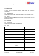
P1D Broadband Module Integration 3 Module Connections 3.1 Data Interface J2 The IPWireless P1D Broadband module is provided with an 18 pin data connector for connection to the external application. This connection supports the following interface types and these are described below. 3.1.1 Universal Serial Bus The data interface provides a USB 1.1 interface. This is available on pins 1-4 of the data connector. 3.1.
P1D Broadband Module Integration 15 Serial CTS 16 Serial TXD 17 DTE Ground 18 Chassis Ground G1, G2 Chassis Ground Table 1: 18 way Data Connector 3.3 DC Power Input J1 The module requires a DC supply of 5VDC at upto 1A, the input voltage is required to be with ±5% of nominal voltage. The connector type is a standard DC plug for 0.65mm centre pin configured as centre positive. 3.
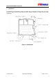
P1D Broadband Module Integration 4 Mechanical The IPWireless P1D Broadband module is provided with 3 designated mounting points, the board should be rigidly mounted using stand-offs with a minimum clearance of 10mm from any other components.
P1D Broadband Module Integration 5 5.1 Regulatory Information Compliance with FCC Rules and Regulations The IPWireless P1D Broadband module is certified against FCC Part 27 for operation in the 24962690MHz frequency allocation. The module is certified under FCC ID: PKTP1DKF2 and is only certified for use with either an integral or external antenna, the maximum antenna gain allowed is defined on the FCC Grant of Certification.