
User's Manual
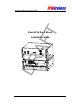


Node B Rack Mount Installation Guide
Version 0.0.0 Page 4 of 42
Table of Tables
Table 2-1 : Safety Sumbols ....................................................................................................6
Table 5-1 : Specifications.......................................................................................................8
Table 5-2 : Node B Model Types..........................................................................................10
Table 6-1 : Digital Shelf - Packing List..................................................................................14
Table 6-2 : Radio Shelf - Packing List...............................................................................15
Table 6-3 : Tools Required...................................................................................................17
Table 6-4 : Materials Required.............................................................................................17
Table 6-5 : Site Preparation Checklist..................................................................................18
Table 6-6 : Ethernet Pin-outs using RJ45.............................................................................30
Table 6-7 : T1/E1 Pin-outs ...................................................................................................31
Table 6-8 : Alarm Inputs.......................................................................................................34
Table 6-9 : Alarm Outputs ....................................................................................................34
Table of Figures
Figure 5-1 : Node B Rack Mount – Digital Shelf Physical Dimensions ...................................8
Figure 5-2 : Node B Rack Mount – RF Shelf Physical Dimensions ........................................9
Figure 5-3 : General Description – Front View .....................................................................10
Figure 5-4 : Digital Shelf Faceplate ......................................................................................11
Figure 5-5 : Radio Shelf Faceplate .................................................................................12
Figure 6-1 : Sales Pack Crate – Digital & Radio Shelf Packages
....................................15
Figure 6-2 : Digital Shelf Package + Contents .................................................................16
Figure 6-3 : Radio Shelf Package + Contents ..................................................................16
Figure 6-4 : Node B Rack Mount – Single Support Shelf (all cables shown)
.................19
Figure 6-5 : Node B Rack Mount – Double Support Shelf (all cables shown) ...............19
Figure 6-6 : Mounting Rack + Support Shelves/Rails...........................................................21
Figure 6-7: Installing Digital Shelf
....................................................................................22
Figure 6-8 : Installing Radio Shelf ........................................................................................23
Figure 6-9 : Earth Connection on the rear of each shelf.......................................................24
Figure 6-10 : Power Connection to the digital shelf ..............................................................25
Figure 6-11 : Power Connection to the radio shelf ...............................................................26
Figure 6-12: Interface Cable Connection – V4A...................................................................27
Figure 6-13: Interface Cable Connection – V4B & V4C........................................................28
Figure 6-14 : Backhaul Connections ..........................................................................29
Figure 6-15 : Ethernet Pin-outs using RJ45 .........................................................................30
Figure 6-16 : Antenna Connections & Routing ................................................................32
Figure 6-17 : Alarm Outputs & Inputs...................................................................................33
Figure 6-18 : GPS Antenna..................................................................................................35
Figure 6-19 : GPS Antenna Connection ...........................................................................36
Figure 6-20 : TTLNA Connections ....................................................................................37