
Installation Guide
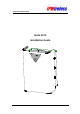

Node B Installation Guide
Version 5.0.0 Page 4 of 15
Table of Tables
Table 2-1 : Safety Sumbols......................................................................................................6
Table 5-1 : Specifications.........................................................................................................8
Table 5-2 : Node B Model Types .............................................................................................9
Table 6-1 : Packing List..........................................................................................................11
Table 6-2 : Tools Required.....................................................................................................12
Table 6-3 : Materials Required...............................................................................................12
Table 6-4 : Site Preparation Checklist ...................................................................................13
Table 6-5 : T1/E1 Pin-outs .......................................................Error! Bookmark not defined.
Table of Figures
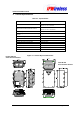
Figure 5-1 : Node B Physical Dimensions ...............................................................................8
Figure 5-2 : General Description..............................................................................................9
Figure 6-1 : Unpacking Sequence ......................................................................................11
Figure 6-2 : Node B - Positioning Clearance .........................................................................14
Figure 6-3 : Mounting Bracket................................................................................................15
Figure 6-4: Drill template.......................................................Error! Bookmark not defined.
Figure 6-5 : Bracket Fixing to Wall - Wall.................................Error! Bookmark not defined.
Figure 6-6: Node B Securing to Uneven Wall..........................Error! Bookmark not defined.
Figure 6-7 : Pole Mounting using Unistrut systems .................Error! Bookmark not defined.
Figure 6-8 : Node B - Rack Mounted .......................................Error! Bookmark not defined.
Figure 6-9: Flexible Conduit.....................................................Error! Bookmark not defined.
Figure 6-10: Node B onto Mounting Bracket............................Error! Bookmark not defined.
Figure 6-11 : Earth Connection................................................Error! Bookmark not defined.
Figure 6-12 : Service Access...................................................Error! Bookmark not defined.
Figure 6-13 : Service Area Description....................................Error! Bookmark not defined.
Figure 6-14 : Power Connections ............................................Error! Bookmark not defined.
Figure 6-15 : Backhaul Connections........................................Error! Bookmark not defined.
Figure 6-16 : Ethernet Pin-outs using RJ45.............................Error! Bookmark not defined.
Figure 6-17 : Ethernet Pin-outs using RJ45.............................Error! Bookmark not defined.
Figure 6-18 : Antenna Connections .....................................Error! Bookmark not defined.
Figure 6-19 : Alarm Outputs & Inputs ......................................Error! Bookmark not defined.
Figure 6-20 : GPS Antenna......................................................Error! Bookmark not defined.
Figure 6-21 : Solar Shield Fitting .............................................Error! Bookmark not defined.
Figure 6-22 : Solar Shield Securing.........................................Error! Bookmark not defined.
Figure 6-23 : Solar Shield Hooked on Node B.........................Error! Bookmark not defined.