
Installation Guide

Node B Installation Guide
Version 5.0.0 Page 13 of 15
Step 3 Site Preparations for Node B Installation
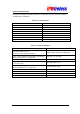
The section specifies the facilities that need to be available at the site prior to installation. The
table below is a site checklist that should be completed prior to installation.
It is assumed that the site has already been selected from RF network planning and that site
acquisition or permission has been granted.
Table 6-4 : Site Preparation Checklist
# Facility Complete
Yes/No
1 Mains power supply –48Vdc
2 Availability of suitable Ethernet, E1, T11, E3 or T3 Interfaces
3 connections and trunking/conduits for interfaces
4 Suitable earth
5 Structure suitable to mount the NodeB
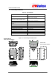
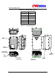
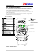
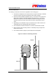
6 Clearance around the NodeB for cable entry and cooling
- see figure below
Assumptions
It is assumed that prior to Node B installation all civil, electrical distribution, structured
cabling termination work has been completed.
Additionally, all antenna rigging, feeder runs and terminations, associated lightning
protection and earthing, has been done, with certification for safety / compliance issued as
required by local regulations.
It is also strongly recommended that all VSWR plots of the feeder / antenna installations
should be available for inspection.
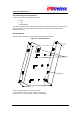
Positioning the Node B
Depending on the flatness of the wall the bracket can either be mounting directly to the wall
or can be mounted offset from the wall using 'Unistrut'.
Selection of a suitable position for the Node B shall be done by surveying possible sites with
regard to the availability of facilities i.e. power, relative position to the INC and consulting the
site plans.
The Node B should be sited not more than 100m from the INC using Shielded Category 5
Ethernet cable as specified. Care should be taken to position the Node B where it can be
easily accessed via the front access cover.
The Node B will need to be connected near the feeder terminations and earthing points as
provided on site.
Note: Where the Node B is installed using a microwave link ensure that the microwave link
can support the Ethernet requirements for the IUB interface i.e. 10 or 100 Mbps / full / half
duplex as the Node B and INC may need to be configured manually in order to support this
configuration.