
Installation Guide

Node B Installation Guide
Version 5.0.0 Page 30 of 37
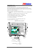
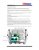
Step 13 Alarm Connections
If local alarms are to be utilised a terminal block has been provided on the Node B
termination panel. The specifications for those interface requirements are below:-
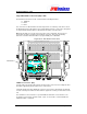
External alarm inputs are connected via connector J11 and the door interlock micro-switch is
connected via connector J10. Connectors J12 and J13 are used for the external alarm
outputs.
The maximum input voltage is restricted to 39V for a 500A 8/20 uS pulse, with a minimum
working voltage of 18V. All six input circuits are the same.
Alarm Inputs
The external alarm inputs shall be opto-isolated current loops. The voltage and currents
shall be supplied by the external source.
Alarm Outputs
The external alarm outputs shall be isolated normally-open relay contacts capable of
switching 100mA DC.
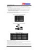
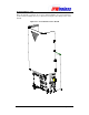
The connectors are 12way (alarm inputs) and 2ways for the alarm outputs, 2.5mm pitch
header that mate with the supplied cable mount - tension clamp, provided in a kit with the
Node B. There are additional strain relief kits also provided within the alarm kit.
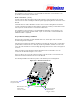
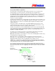
The cable should be fed through the sealing cable glands assembly and the base of the
casting. Then the cables should be stripped 5-6mm and inserted into the connector prior to
mating with the NodeB.
The cable gland to seal plus strain relief the cable is as illustrated for the
power connection above.
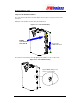
The signals are paired starting from the right, pin1 is the right-hand-side on each connector.
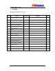
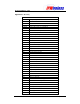
Figure 6-19 : Alarm Outputs & Inputs
Alarm Outputs
Alarm Inputs