
User's Manual Part 2


Node B Rack Mount Installation Guide
Version 0.0.3 Page 33 of 39
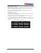
Alarm Inputs
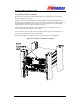
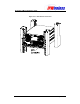
The 6 external alarm inputs are connected via the 15wayD female type located on the right
hand side of the digital shelf.
The external alarm inputs are opto-isolated current loops. The voltage and currents shall be
supplied by the external source.
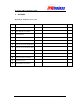
The pin-out for the alarm inputs are shown in the table below.
Table 6-7 : Alarm Inputs
Pin
#
Signal
1 ALARM_IN_A0
2 ALARM_IN_B0
3 ALARM_IN_A1
4 ALARM_IN_B1
5 ALARM_IN_A2
6 ALARM_IN_B2
7 ALARM_IN_A3
8 ALARM_IN_B3
9 Earth
10 ALARM_IN_A4
11 ALARM_IN_B4
12 ALARM_IN_A5
13 ALARM_IN_B5
14 Earth
15 Earth
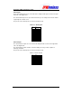
Alarm Outputs
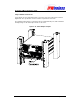
The external alarm outputs are connected via the 9wayD female located on the right hand
side of the digital shelf.
The external alarm outputs shall be isolated normally-open relay contacts capable of
switching 100mA DC.
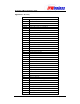
The pin-out for the alarm inputs are shown in the table below.
Table 6-8 : Alarm Outputs
Pin Signal
1 ALARM_OUT0+
2 ALARM_OUT0-
3 Earth
4 ALARM_OUT0+
5 ALARM_OUT0-
6 Earth
7 Earth
8 Earth
9 Earth