
User's Manual Part 1


Node B Rack Mount Installation Guide
Version 0.0.3 Page 4 of 39
Table of Tables
Table 2-1 : Safety Sumbols ..................................................................................................... 6
Table 5-1 : Specifications ........................................................................................................ 8
Table 5-2 : Node B Model Types........................................................................................... 10
Table 6-1 : Packing List......................................................................................................... 14
Table 6-2 : Tools Required.................................................................................................... 17
Table 6-3 : Materials Required .............................................................................................. 17
Table 6-4 : Site Preparation Checklist................................................................................... 18
Table 6-5 : Ethernet Pin-outs using RJ45 ............................................................................. 29
Table 6-6 : T1/E1 Pin-outs..................................................................................................... 30
Table 6-7 : Alarm Inputs ........................................................................................................ 33
Table 6-7 : Alarm Outputs ..................................................................................................... 33
Table of Figures
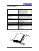
Figure 5-1 : Node B Rack Mount – Digital Shelf Physical Dimensions ................................... 8
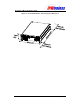
Figure 5-2 : Node B Rack Mount – RF Shelf Physical Dimensions ........................................ 9
Figure 5-3 : General Description – Front View...................................................................... 10
Figure 5-4 : Digital Shelf Faceplate ....................................................................................... 11
Figure 5-5 : Radio Shelf Faceplate
.................................................................................. 12
Figure 6-1 : Sales Pack Crate – Digital & Radio Shelf Packages
.................................... 15
Figure 6-2 : Digital Shelf Package + Contents
.................................................................. 15
Figure 6-3 : Radio Shelf Package + Contents ................................................................... 16
Figure 6-4 : Node B Rack Mount – Single Shelf (all cables shown)
............................... 19
Figure 6-5 : Node B Rack Mount – Double Shelf (all cables shown)
.............................. 19
Figure 6-6 : Mounting Rack + Support Shelves/Rails ........................................................... 21
Figure 6-7: Installing Digital Shelf...................................................................................... 22
Figure 6-8 : Installing Radio Shelf ......................................................................................... 23
Figure 6-9 : Earth Connection on the rear of each shelf ....................................................... 24
Figure 6-10 : Power Connection to the digital shelf............................................................... 25
Figure 6-11 : Power Connection to the radio shelf................................................................ 26
Figure 6-12: Interface Cable Connection .............................................................................. 27
Figure 6-13 : Backhaul Connections
................................................................................ 28
Figure 6-15 : Ethernet Pin-outs using RJ45 .......................................................................... 29
Figure 6-15 : Antenna Connections & Routing
................................................................. 31
Figure 6-17 : Alarm Outputs & Inputs.................................................................................... 32
Figure 6-18 : GPS Antenna ................................................................................................... 34
Figure 6-18 : GPS Antenna Connection
............................................................................ 35