
Installation Manual
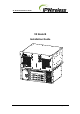


V5 Node B Installation Guide
Version 1.0.6 Page 10 of 44
4. General Specifications
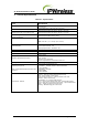
Table 4-1 : Specifications
Unit
Specification
Rack Specifications
19inch Mounting Racks with support shelves
Front Securing
Measurements – incl front brackets
Control Shelf: 180 H / (4U) x 485 W x 310 D mm
Radio Equipment Shelf: 222 H/(5U) x 485 W x 380 D mm
Measurements with front handles & cable
Control Shelf: 180 H / (4U) x 485 W x 510 D mm
Radio Equipment Shelf: 222 H/(5U) x 485 W x 510 D mm
Node B Weight
Control Shelf: ≤13Kgs / 28 lbs
Radio Equipment Shelf: ≤25kgs / 55 lbs
Power Consumption
Control Shelf: 350 Watts max (8Amp Fused).
Note: Fuse Size: ( ¼ x 1 ¼ inch) / (6.3 x 32 mm)
Heat Dissipation
Control Shelf 350 Watts - max
Radio Equipment Shelf – 600 Watts - max
Input Power Nominal
-48 V DC
Input Range
-36V to -70V DC
Ambient Operational Environment
-20ºC to +55ºC
0 to 95% Relative Humidity- Non-condensing
IP20 – IEC529
No water or Ice precipitation
All other requirements to ETS300-019 Class 3.1E
Cooling
Forced Convection – Fan Assisted
Cool Air Intake front & Exhaust rear
Operating Frequencies
Note: Variant Radio Equipment shelf for each
frequency
a) 2496 MHz – 2690 MHz
b) 1900MHz – 1920MHz (20MHz or 5MHz bandwidths)
c) 2010-2025MHz
d) 3400MHz – 3615MHz
e) 698-798MHz
f) 2305-2360MHz
Connections - External
Antenna – DIN 7/16 Female (Radio Equipment shelf)
GPS – N-type Female ( Control shelf)
Power Circular Connectors – cables provided for each shelf
Ethernet – RJ45 ( Control shelf)
Optical MMF - LC-LC Duplex OM2 50/125um
E1/T1 – RJ45 ( Control shelf-Control Card) – optional PMC module
E3/T3 – BNC 75Ω ( Control shelf-Control Card) – optional PMC module
Alarm – 15wayD ( Control shelf-Control Card)
Earthing – M8 Bolt hole @ rear of each shelf