
User Manual

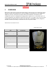
Table Of Contents
- IMPORTANT
- Legal Terms Governing This Document
- 1 OVERVIEW
- 2 PRE-INSTALLATION
- (Step 3) MOUNTING THE NODE B BRACKET
- 4 Site Preparation for Node B Installation
- 5 (Step 10) PHYSICAL INSTALLATION OF THE NODE B
- 5.1 Placing the Node B into the Rack
- 5.2 Service Area Interfaces
- 5.3 (Step 6) Grounding Installation and Inspection
- 5.4 Cable Clamp Seal
- 5.5 Connecting Power to the Node B
- Backhaul Connections to INC
- 5.7 Alarm Connections
- 5.8 Replacement of the Seal cable clamp
- 5.9 Conduit Pivot Bracket Securing
- 5.10 Closing the Door and securing the NodeB
- 5.11 GPS
- 6 (Step 11) Power up and Initial Setup of Node B
- 8
- 8 (Step 12) SOFTWARE INSTALLATION
- 9 (Step 13) On Air final check
- 10 Operation & Maintenance

Node B Installation Guide
DRAFT
17 July, 2001 IPWireless Proprietary
IT IS ILLEGAL TO MAKE COPIES OF THIS DOCUMENT WITHOUT EXPRESS PERMISSION BY IPWIRELESS
8
1 OVERVIEW
Node B is the European Technical Standards Institute’s (ETSI) name for the radio base station.
The basic function of the Node B is to convert 100 Base T packet data into the UTRAN TD-
CDMA air interface used between the Node B and the 3G Modem. The Node B can be
configured to operate in configurations ranging from a single sector or omni mode, up to a 6
sector arrangement. One Node B is required for each sector of coverage, in the case of an omni
configuration one Node B will be required. The Node B is controlled by an INC (Integrated
network Controller) Generally co located at the site in a separate cabinet.
N
ODE
B H
IGH
L
EVEL
S
PECIFICATIONS
N
ODE
B F
RONT
V
IEW
Unit Specification
Measurements 16” H x 12” W x 5” D
Weight with mounting
Bracket
40 Pounds
Frequency 2500 – 2686 MHz
Power output +34 dBm
Power Consumption 300 Watts max
Input Power 110 VAC or -48 V DC
Heat Dissipation 184 Watts
Ambient Operational Temp
Range
-40ºC to +55ºC
Cooling Convection
Weight 42 lbs.