
User Manual
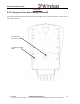


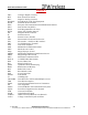
Table Of Contents
- IMPORTANT
- Legal Terms Governing This Document
- 1 OVERVIEW
- 2 PRE-INSTALLATION
- (Step 3) MOUNTING THE NODE B BRACKET
- 4 Site Preparation for Node B Installation
- 5 (Step 10) PHYSICAL INSTALLATION OF THE NODE B
- 5.1 Placing the Node B into the Rack
- 5.2 Service Area Interfaces
- 5.3 (Step 6) Grounding Installation and Inspection
- 5.4 Cable Clamp Seal
- 5.5 Connecting Power to the Node B
- Backhaul Connections to INC
- 5.7 Alarm Connections
- 5.8 Replacement of the Seal cable clamp
- 5.9 Conduit Pivot Bracket Securing
- 5.10 Closing the Door and securing the NodeB
- 5.11 GPS
- 6 (Step 11) Power up and Initial Setup of Node B
- 8
- 8 (Step 12) SOFTWARE INSTALLATION
- 9 (Step 13) On Air final check
- 10 Operation & Maintenance

Node B Installation Guide
DRAFT
17 July, 2001 IPWireless Proprietary
IT IS ILLEGAL TO MAKE COPIES OF THIS DOCUMENT WITHOUT EXPRESS PERMISSION BY IPWIRELESS
41
APPENDIX D – Node B SPECIFICATIONS
Size 16” H x 12” W x 5” D
Weight 42 Pounds
RF Power output +34 dBm composite (maximum)
Receive Sensitivity -110 dBm/6 MHz channel
Antenna connector type N F X 3 (Tx, Tx/Rx, GPS receiver)
Maximum antenna line loss 2 dB suggested
Power consumption 300 Watts maximum
Voltage requirement -48 VDC or 110 VAC (Optioned at time of order)
Head Disipation 184 Watts
Backhaul facility throughput 6 Mbps downlink, 3 Mbps uplink
Backhaul facility type 4 X T1, 100BT Ethernet
LMT interface 10/100BT Ethernet
Frequency Range 2500 MHz – 2686 MHz
Bandwidth 12 MHz
Air Interface UTRAN TD-CDMA
Duplex method Time division
Chipping Rate 7.68 Mcps
Spreading Codes OVSF
Maximum Path loss 150 Db
Error Correction variable punctured Turbo coding
Spreading factor variable - 4, 8 and 16
Modulation QPSK