
User Manual
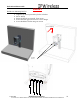
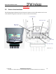
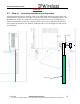
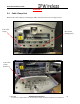
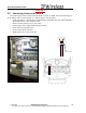
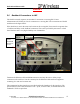
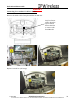
Table Of Contents
- IMPORTANT
- Legal Terms Governing This Document
- 1 OVERVIEW
- 2 PRE-INSTALLATION
- (Step 3) MOUNTING THE NODE B BRACKET
- 4 Site Preparation for Node B Installation
- 5 (Step 10) PHYSICAL INSTALLATION OF THE NODE B
- 5.1 Placing the Node B into the Rack
- 5.2 Service Area Interfaces
- 5.3 (Step 6) Grounding Installation and Inspection
- 5.4 Cable Clamp Seal
- 5.5 Connecting Power to the Node B
- Backhaul Connections to INC
- 5.7 Alarm Connections
- 5.8 Replacement of the Seal cable clamp
- 5.9 Conduit Pivot Bracket Securing
- 5.10 Closing the Door and securing the NodeB
- 5.11 GPS
- 6 (Step 11) Power up and Initial Setup of Node B
- 8
- 8 (Step 12) SOFTWARE INSTALLATION
- 9 (Step 13) On Air final check
- 10 Operation & Maintenance

Node B Installation Guide
DRAFT
17 July, 2001 IPWireless Proprietary
IT IS ILLEGAL TO MAKE COPIES OF THIS DOCUMENT WITHOUT EXPRESS PERMISSION BY IPWIRELESS
26
5.5 Connecting Power to the Node B
The power supply can be either universal ACDC coverter of 300W, universal input range of
90 to 240Vac with a 12Vdc output or a –48Vdc input to 12Vdc output.
• Cable preparation – Specification: terminal blocks maximum cable size 2mm
2
(14AWG)
& maximum size of outer diameter 7mm.
• Remove mains protective cover (2 screws)
• Loosen strain relief Clamp Earth Clamp (2 screws)
• Insert cable into terminal block
• Secure strain relief (2 screws)
• Replace protective cover (2 screws)
Mains
Cable Clamp