
Installation Guide

V5 Node B Installation Guide
Version 1.0.5 Page 37 of 44
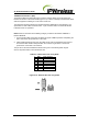
Alarm Inputs
There are five external alarm inputs are connected via the 15wayD male type located on the
Control Card of the Control shelf.
The maximum input voltage is restricted to 12V and 2.5mA with a minimum
working voltage of 6V. All five input circuits are the same.
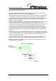
The external alarm inputs are opto-isolated current loops. The voltage and currents shall be
supplied by the external source.
The pin-out for the alarm inputs are shown in the table below.
Table 5-8 : Alarm Inputs & Outputs
Pin
#
Signal
4 ALARM_IN_A0 +
11 ALARM_IN_B0 -
5 ALARM_IN_A1 +
12 ALARM_IN_B1 -
6 ALARM_IN_A2 +
13 ALARM_IN_B2 -
7 ALARM_IN_A3 +
14 ALARM_IN_B3 -
1 ALARM_OUT_A0 +
9 ALARM_OUT_B0 -
2 ALARM_OUT_A1 +
10 ALARM_OUT_B1 -
15 Earth
GND D-Shell /Chassis GND
Alarm Outputs
The external alarm outputs are connected via the same 15wayD male located on the Control
Card of the Control shelf.
The external alarm outputs shall be isolated normally-open relay contacts capable of
switching 100mA DC.
The pin-out for the alarm inputs are shown in the table above.