
Installation Guide

V5 Node B Installation Guide
Version 1.0.5 Page 34 of 44
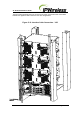
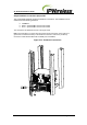
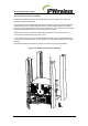
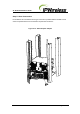
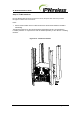
E3/T3 Connections – (Tx + Rx)
Terminate the E3/T3 cables with BNC connectors and the cables may be secured to the brackets
on the face of the Digital Shelf (
Figure 5-13). Test the continuity for the E3/T3 cables with test
equipment consisting of a main and a remote unit.
The termination for these interfaces is specified within the datasheets for the interfaces. The
specification for both cables should be 75.
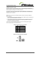
E1/T1 Connections – (1 to 4)
Terminate the E1/T1 cables with RJ45 connectors and the cables may be secured to the brackets
on the face of the Digital Shelf (
Figure 5-13).
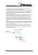
Test the continuity for the E1/T1 cables with test equipment consisting of a main and a remote
unit. The pin-outs for this interface are shown in the table below.
The termination for these interfaces is specified within the datasheets for the interfaces. The
specification for both cables should be E1/T1 RJ48C, 24AWG solid, 120 , Straight-thru
cable, each pair individually, screened cable, recommended SC-7348 Stonewall Cable Inc,
or equivalent.
Table 5-7 : T1/E1 Pin-outs (RJ48C)
T1 Pin-outs Cable E1 Pin-outs
1
Rx (ring) White w/Green Rx (ring)
1
2
Rx (tip) Green Rx (tip)
2
3
Not used White w/Orange Not used
3
4
Tx (ring) Blue Tx (ring)
4
5
Tx (tip) White w/Blue Tx (tip)
5
6
Not used Orange Not used
6
7
Not used White w/Brown Not used
7
8
Not used Brown Not used
8