
Installation Guide
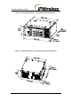


V5 Node B Installation Guide
Version 1.0.5 Page 19 of 44
In addition to standard construction equipment, the following tools and materials should be
available prior to installation:
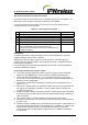
Table 5-3 : Tools Required
Tools Description/Use
Basic telecommunications tool kit Includes screwdriver, socket wrenches, etc.
Voltmeter Fluke meter
Cable Stripper & Crimper RJ 45 crimper connector
Ethernet cable test set Test for all Ethernet cables
Handheld GPS with signal indicator Test for GPS signal at site location
Compass Establish antenna directions
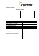
Table 5-4 : Materials Required
Material
Description
CAT5 - 4 pair, double screened cable, recommended
Alcatel LANmark-5 F
2
TP or equivalent
IUB / LMT
RJ48C, 24AWG solid, 120 , Straight-thru cable, each
pair individually, screened cable
T1 / E1 Cable
RJ45 Connectors IUB / LMT (optional T1 / E1 Connections)
CAT5 - 4 pair, double screened cable, recommended
Alcatel LANmark-5 F
2
TP or equivalent
Alarm distribution cable
33mm
2
maximum Ground cable (2AWG)
Grounding termination
M8 ring terminal Grounding termination
BNC Right Angle Connectors (75) Connectors for E3/T3 Connections (optional)
RG59 B/U-LSF and UV stabilised or equivalent Cable for E3/T3 Connections
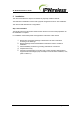
Rack mounting cage nuts + screws – note these are
required to secure the shelves to the rack
typically M6 Thread screws, washers & rack
cage nuts
Rack/Cabinet or Enclosure
Installation and/or site specific
Shelf Supports or rails
Specific to rack/cabinet or enclosure
DIN 7/16 antenna connections
Connectors specific to antenna cable chosen
Antenna Cable
Site specific selection