
Install Manual


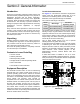

Table Of Contents
- Table of Contents
- Section 1: Safety
- Section 2: General Information
- Section 3: Installation
- Section 4: Operation
- Section 5: Drawings and Diagrams
- Installation Drawing—100A SE & Non-SE/150-200A Non-SE
- Installation Drawing—150/200A SE
- Installation Drawing—Liquid Cooled Generator
- Installation Drawing—Liquid-Cooled Generator
- Installation Drawing—Air-Cooled Generator SE and Non-SE Rated ATS
- Installation Drawing—Air-Cooled Generator SE and Non-SE Rated ATS

General Information
Automatic Transfer Switch Owner’s Manual 5
Section 2: General Information
Introduction
Thank you for purchasing a Generac transfer switch. This
manual has been prepared especially for the purpose of
familiarizing personnel with the design, application,
installation, operation and servicing of the applicable
equipment. Read this manual carefully and comply with
all instructions. This will help to prevent accidents or
damage to equipment that might otherwise be caused by
carelessness, incorrect application, or improper
procedures.
Every effort has been expended to make sure that the
contents of this manual are both accurate and current.
The manufacturer, however, reserves the right to change,
alter or otherwise improve the product or manual at any
time without prior notice.
Unpacking
Carefully unpack the transfer switch. Inspect closely for
any damage that might have occurred during shipment.
The purchaser must file with the carrier any claims for
loss or damage incurred while in transit.
Check that all packing material is completely removed
from the switch prior to installation.
Contents in Loose Parts Bag
• Owner’s manual
• Warranty statement
• Manual operating handle
• Storage bracket for manual operating handle
• Fault current label
• Clear decal for fault current label
Equipment Description
This automatic transfer switch is used for transferring
electrical load from a utility (normal) power source to a
generator (standby) power source. Transfer of electrical
loads occurs automatically when the utility power source
has failed or is substantially reduced and the generator
source voltage and frequency have reached an
acceptable level. The transfer switch prevents electrical
feedback between two different power sources (such as
the utility and generator sources) and, for that reason,
codes require it in all standby electric system installations.
The transfer switch consists of a transfer mechanism,
utility service disconnect circuit breaker (if equipped), and
a Smart A/C module incorporating fuses and two terminal
blocks for transfer switch connections.
Transfer Switch Mechanism
See Figure 2-1. This switch is used with a single-phase
system when the single-phase neutral line is to be
connected to a neutral lug and is not to be switched.
Solderless, screw-type terminal lugs are standard.
The conductor size range is as follows:
This transfer switch is suitable for control of motors, electric
discharge lamps, tungsten filament and electric heating
equipment where the sum of motor full load ampere ratings
and the ampere ratings of other loads do not exceed the
ampere rating of the switch and the tungsten load does not
exceed 30 percent of the switch rating.
This UL listed transfer switch is for use in optional
standby systems only (NEC article 702).
A 100A rated switch is suitable for use on circuits capable
of delivering not more than 10,000 RMS symmetrical
amperes, 250 VAC maximum, when protected by a 100A
maximum circuit breaker (Siemens types QP or BQ) or
150A maximum circuit breaker (Square D Q2,
Westinghouse CA-CAH, General Electric TQ2 and
Siemens QJ2).
A 200A rated switch is suitable for use on a circuit
capable of 22,000 RMS symmetrical amperes, 240 VAC
when protected by a circuit breaker without an adjustable
short time response or by fuses.
Figure 2-1. Typical Single-Phase ATS Transfer
Mechanism
Switch
Rating
Wire Range
Conductor
Tightening Torque
100A #14-1/0 AWG (Cu/Al) 50 in-lbs (5.6 Nm)
150/200A #6-250 MCM (Cu/Al) 275 in-lbs (31 Nm)
000219
A
B
C
D
E