
Product Manual


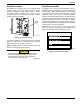


Table Of Contents
- Owner’s Manual For PWRview™ Automatic Transfer Switch
- Table of Contents
- Section 1 Safety
- Section 2: General Information
- Section 3: Installation
- Section 4: Operation
- Functional Tests and Adjustments
- Manual Operation
- Voltage Checks
- Generator Tests Under Load
- Checking Automatic Operation
- Installation Summary
- Shutting Generator Down While Under Load or During a Utility Outage
- Preparing for Maintenance
- Testing The SACM
- SACM Fuse Service
- Testing The SMM
- PWRview Monitor Operation
- PWRview Monitor Reset
- PWRview Fuse Replacement
- Section 5: Drawings and Diagrams

Installation
12 Automatic Transfer Switch Owner’s Manual
Figure 3-3. Typical SACM Connections
A
Thermostat 1
B
Air Conditioner 1
C
Thermostat 2
D
Air Conditioner 2
E
Thermostat 3
F
Air Conditioner 3
G
Thermostat 4
H
Air Conditioner 4
I
Spare Fuse Holder
T1 (fused)
Battery Charge
N1 (fused)
Utility Sense
N2 (fused)
Utility Sense
0 DC
Ground
194
+ 12 VDC
23
Transfer Control
J
240 VAC, 6.3A
Fuses
A
B
G
H
C
D
E
F
T1
1
1
1
1
2
2
2
2
T1N1N2
0 DC GROUND
194 +12 VDC
N1
N2
T1
23 TRANSFER
®
®
J
T1
N2
0
194
23
N1
006244
I