
Product Manual


7
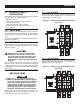
4. With an accurate AC voltmeter and frequency meter, check the
no-load, voltage and frequency.
Single-phase generator supply:
Measure across ATS terminal lugs E1 to E2; E1 to NEUTRAL
and E2 to NEUTRAL.
a. Frequency ....................................................60-62 Hz
b. Terminals E1 to E2 .......................................240-246 VAC
c. Terminals E1 to NEUTRAL ............................120-123 VAC
d. Terminals E2 to NEUTRAL ............................120-123 VAC
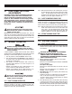
Three-phase generator supply:
Measure across ATS terminal lugs E1 to E2, E2 to E3 and E1
to E3.
Measure across ATS terminal lugs E1 to NEUTRAL, E2 to
NEUTRAL and E3 to NEUTRAL.
a. Frequency ....................................................60-62 Hz
b. Terminals E1-E2, E2-E3, E1-E3 .................... 208-212VAC, 235-
245VAC or 470-
485VAC
c. Terminals E1-N, E2-N, E3-N ......................... 120-122VAC, 136-
140VAC or 272-
282VAC
It will also be necessary to verify that the phase rotation of the util-
ity matches the phase rotation of the generator. This can be done
by using a phase rotation indicator.
Failure to do so may result in damage to cer-
tain rotary equipment.
5. When certain that UTILITY supply voltage is correct and
compatible with transfer switch ratings, turn OFF the UTILITY
supply to the transfer switch.
6. Set the generator’s main circuit breaker (CB1) to its OFF or
OPEN position.
7. Set the Auto/Off/Manual switch to the OFF position to shut
down the generator.
NOTE:
Do NOT proceed until generator AC output voltage and frequen-
cy are correct and within stated limits. If the no-load voltage is
correct but no-load frequency is incorrect, the engine governed
speed probably requires adjustment. If no-load frequency is
correct but voltage is not, the voltage regulator may require
adjustment.
3.4 GENERATOR TESTS UNDER
LOAD
1. Set the generator's main circuit breaker to its OFF or OPEN
position.
2. Manually actuate the transfer switch main contacts to their
emergency (Standby) position. Refer to “Manual Operation”.
3. To start the generator, set the AUTO/OFF/MANUAL switch to
MANUAL. When engine starts, let it stabilize for a few min-
utes.
4. Turn the generator's main circuit breaker to the ON or CLOSED
position. The generator now powers all LOAD circuits. Check
generator operation under load as follows:
• Turn ON electrical loads to the full rated wattage/amper-
age capacity of the generator. DO NOT OVERLOAD.
• With maximum rated load applied, check voltage and
frequency across transfer switch terminals E1 and
E2. Voltage should be greater than 200 volts (208VAC
system) or 230 volts (240VAC system), or 470 volts
(480VAC system); frequency should be greater than 59
Hz.
• Let the generator run under rated load for at least 30 min-
utes. With unit running, listen for unusual noises, vibra-
tion, overheating, etc., that might indicate a problem.
5. When checkout under load is complete, set main circuit
breaker of the generator to the OFF or OPEN position.
6. Let the generator run at no-load for several
minutes. Then, shut down by setting the AUTO/OFF/MANUAL
switch to its OFF position.
7. Move the switch's main contacts back to the
UTILITY position. For example, load connected to utility power
supply. Refer to “Manual Operation”. Handle and operating
lever of transfer switch should be in down position.
8. Turn on the utility power supply to transfer switch, using
whatever means provided (such as a utility main line circuit
breaker). The utility power source now powers the loads.
9. Set the generator's AUTO/OFF/MANUAL switch to its AUTO
position. The system is now set for fully automatic opera-
tion.
Operation