Owner's Manual 400 Amp RTS Automatic Transfer Switch www.generac.
Table of Contents Safety Rules ................................................. Inside Front Cover General Information ................................................................. 2 1.1 Introduction ................................................................................ 2 1.2 Equipment Description ................................................................ 2 1.3 Transfer Switch Data Label.......................................................... 2 1.4 Transfer Switch Enclosure ...
Safety Rules Throughout this publication, and on tags and decals affixed to the generator, DANGER, WARNING, CAUTION and NOTE blocks are used to alert personnel to special instructions about a particular operation that may be hazardous if performed incorrectly or carelessly. Observe them carefully. Their definitions are as follows: After this heading, read instructions that, if not strictly complied with, will result in serious personal injury, including death.
General Information 1.1 INTRODUCTION This manual has been prepared especially for the purpose of familiarizing personnel with the design, application, installation, operation and servicing of the applicable equipment. Read the manual carefully and comply with all instructions. This will help to prevent accidents or damage to equipment that might otherwise be caused by carelessness, incorrect application, or improper procedures.
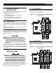
Installation 2.1 INTRODUCTION TO INSTALLATION This equipment has been wired and tested at the factory. Installing the switch includes the following procedures: • • • • • • Mounting the enclosure. Connecting utility and generator power source leads. Connecting the load leads. Connecting any auxiliary contact (if needed) Installing/connecting any options and accessories. Testing functions. 2.2 2.4.1 2-POLE MECHANISM These switches (Figure 2.
Installation Solderless, screw-type terminal lugs are standard. The conductor size range is as follows: Switch Rating Wire Range 400A (1) #4-600 MCM or (2) 1/0-250 MCM Conductor sizes must be adequate to handle the maximum current to which they will be subjected; based on the 75°C column of tables, charts, etc. used to size conductors. The installation must comply fully with all applicable codes, standards and regulations.
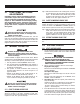
Operation 3.1 FUNCTIONAL TESTS AND ADJUSTMENTS Following transfer switch installation and interconnection, inspect the entire installation carefully. A competent, qualified electrician should inspect it. The installation should comply strictly with all applicable codes, standards, and regulations. When absolutely certain the installation is proper and correct, complete a functional test of the system.
Operation Figure 3.1 — Actuating Transfer Switch NOTE: If the power monitor does not operate properly, check that all three voltages are present, and are of the correct voltage level and phase rotation. To change phase rotation, turn off the utility supply, interchange 2 of the utility power phases. 3.3.2 GENERATOR VOLTAGE CHECKS 1. 2. 3. PLY BEFORE WORKING ON THE UTILITY On the generator panel, set the AUTO/OFF/MANUAL switch to MANUAL position. The generator should crank and start.
Operation 4. With an accurate AC voltmeter and frequency meter, check the no-load, voltage and frequency. Single-phase generator supply: Measure across ATS terminal lugs E1 to E2; E1 to NEUTRAL and E2 to NEUTRAL. a. b. c. d. Frequency ....................................................60-62 Hz Terminals E1 to E2 .......................................240-246 VAC Terminals E1 to NEUTRAL ............................120-123 VAC Terminals E2 to NEUTRAL ............................
Notes 8
Notes 9
Notes 10
277/480V 3-phase - Drawing No.
12 TRIPLE EKO SUITABLE FOR 1", 1.25" & 1.50" CONDUIT 3 PLACES 254mm[10.0"] 917mm[36.1"] 609.6mm[24.0"] 487mm[19.2"] MOUNTING HOLES: Ø6.35mm[Ø0.25"] 4-PLACES 60.8mm[2.4"] 794mm[31.3"] 61.3mm[2.4"] Installation Diagram 120/240V Single-phase & 120/208V 3-phase - Drawing No.
TB1 CUSTOMER CONNECTION 8 7 RM STRT WIRE 178 6 RM STRT WIRE 183 5 TRNS SW WIRE 194 4 TRNS SW WIRE 23 3 UTILITY N2 2 UTILITY N1 1 E2 (E3) NOTE: E3, N3 AND T3 WIRES ARE ONLY USED ON 3 PHASE SYSTEMS E1 E2 NEUTRAL BLOCK E1 POWER LEADS AND TRANSFER SWITCH LEADS MUST BE RUN IN TWO DIFFERENT CONDUITS.
Part No. 0F6351 Revision D (08/06/13) Printed in U.S.A.
1 2 3 4 5 6 7 8 9 10 * 11 12 13 * 14 15 16 17 18 19 20 21 22 23 24 25 26 27 28 29 30 31 32 33 34 35 36 37 38 * 39 40 41 42 43 44 45 * 46 47 48 0D7295 0A7822 026902 0C7907F 024526 057329 027482 022097 0C8275 0D2572 090388 0A1495 063617 085296 0A1661 0C2162 0H15660ST14 0F59480ST14 0C8308 0C2262 0F6165 PER MODEL 064101 0J1003 087680 063378 064761 063321 073590A 083512 067210A 0A9457 0D4545 0J2320 0J1774 0C4981 063306 0F6760 PER MODEL 0D3587 091472 091472A 064126 056893 0H1605 0A8261 022473 0G3274 1 9 5 2 1 1