Technical Manual 400 Amp RTS Automatic Transfer Switch www.generac.
Safety Rules THESE INSTRUCTIONS! Read the following information carefully before attempting to install, operate or service this equipment. Also read the instructions and information on tags, decals, and nSAVE labels that may be affixed to the transfer switch. Replace any decal or label that is no longer legible.
Table of Contents • If work must be done on this equipment while standing on metal or concrete, place insulative mats over a dry wood platform. Work on this equipment only while standing on such insulative mats. • Never work on this equipment while physically or mentally fatigued. • Keep the transfer switch enclosure door closed and bolted at all times. Only qualified personnel should be permitted access to the switch interior.
General Information 1.1 INTRODUCTION This manual has been prepared especially for the purpose of familiarizing personnel with the design, application, installation, operation and servicing of the applicable equipment. Read the manual carefully and comply with all instructions. This will help to prevent accidents or damage to equipment that might otherwise be caused by carelessness, incorrect application, or improper procedures.
Installation 2.1 INTRODUCTION TO INSTALLATION This equipment has been wired and tested at the factory. Installing the switch includes the following procedures: • • • • • • Mounting the enclosure. Connecting utility and generator power source leads. Connecting the load leads. Connecting any auxiliary contact (if needed) Installing/connecting any options and accessories. Testing functions. 2.2 2.4.1 2-POLE MECHANISM These switches (Figure 2.
Installation Solderless, screw-type terminal lugs are standard. The conductor size range is as follows: Switch Rating Wire Range 400A (1) #4-600 MCM or (2) 1/0-250 MCM Conductor sizes must be adequate to handle the maximum current to which they will be subjected; based on the 75°C column of tables, charts, etc. used to size conductors. The installation must comply fully with all applicable codes, standards and regulations.
Operation 3.1 FUNCTIONAL TESTS AND ADJUSTMENTS Following transfer switch installation and interconnection, inspect the entire installation carefully. A competent, qualified electrician should inspect it. The installation should comply strictly with all applicable codes, standards, and regulations. When absolutely certain the installation is proper and correct, complete a functional test of the system.
Operation Figure 3.1 — Actuating Transfer Switch NOTE: If the power monitor does not operate properly, check that all three voltages are present, and are of the correct voltage level and phase rotation. To change phase rotation, turn off the utility supply, interchange 2 of the utility power phases. PLY BEFORE WORKING ON THE UTILITY OUTPUT VOLTAGE IS NOW BEING PROCEED WITH CAUTION. GENERATOR FAILURE TO TURN OFF THE UTILITY SUP- 5.
Operation b. Terminals E1-E2, E2-E3, E1-E3 ....................208-212VAC, 235245VAC or 470485VAC c. Terminals E1-N, E2-N, E3-N .........................120-122VAC, 136140VAC or 272282VAC It will also be necessary to verify that the phase rotation of the utility matches the phase rotation of the generator. This can be done by using a phase rotation indicator. 3.4 1. 2. 3. 4. to do so may result in damage to certain rotary equipment. nFailure 5. 6. 7.
Notes 8
Notes 9
Notes 10
277/480V 3-phase - Drawing No.
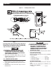
12 TRIPLE EKO SUITABLE FOR 1", 1.25" & 1.50" CONDUIT 3 PLACES 254mm[10.0"] 917mm[36.1"] 609.6mm[24.0"] 487mm[19.2"] MOUNTING HOLES: Ø6.35mm[Ø0.25"] 4-PLACES 60.8mm[2.4"] 794mm[31.3"] 61.3mm[2.4"] Installation Diagram 120/240V Single-phase & 120/208V 3-phase - Drawing No.
TB1 CUSTOMER CONNECTION 8 7 RM STRT WIRE 178 6 RM STRT WIRE 183 5 TRNS SW WIRE 194 4 TRNS SW WIRE 23 3 UTILITY N2 2 UTILITY N1 1 E2 (E3) NOTE: E3, N3 AND T3 WIRES ARE ONLY USED ON 3 PHASE SYSTEMS E1 E2 NEUTRAL BLOCK E1 POWER LEADS AND TRANSFER SWITCH LEADS MUST BE RUN IN TWO DIFFERENT CONDUITS.
Electrical Data 400A, 120/240V, 2-pole Switch - Drawing No.
Electrical Data 400A, 120/240V, 2-pole Switch - Drawing No.
Electrical Data 400A, 120/208V, 3-pole Switch - Drawing No.
Electrical Data 400A, 120/208V, 3-pole Switch - Drawing No.
Electrical Data 18 400A, 277/480V, 3-pole Switch - Drawing No.
400A, 277/480V, 3-pole Switch - Drawing No.
Exploded Views & Parts Lists 20 400A, 120/240V, 2-pole Assembly Drawing No.
400A, 120/240V, 2-pole Assembly Drawing No. 0F6274$-E ITEM PART NO. QTY.
Exploded Views & Parts Lists 22 400A, 120/208V, 3-pole Assembly Drawing No.
400A, 120/208V, 3-pole Assembly Drawing No. 0F6276$-F ITEM PART NO. QTY.
Exploded Views & Parts Lists 24 400A, 277/480V, 3-pole Assembly Drawing No.
400A, 277/480V, 3-pole Assembly Drawing No. 0J1006$-A ITEM PART NO. QTY.
Warranty GENERAC POWER SYSTEMS STANDARD TWO-YEAR LIMITED WARRANTY FOR GENERAC EMERGENCY TRANSFER SWITCH SYSTEMS NOTE: ALL UNITS MUST HAVE A START-UP INSPECTION PERFORMED BY AN AUTHORIZED GENERAC DEALER. For a period of two (2) years of operation from the date of start up, Generac Power Systems, Inc.