
Product Manual

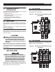
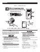

Table Of Contents

5
3.1 FUNCTIONAL TESTS AND
ADJUSTMENTS
Following transfer switch installation and inter-
connection, inspect the entire installation care-
fully. A competent, qualified electrician should
inspect it. The installation should comply strictly
with all applicable codes, standards, and regula-
tions. When absolutely certain the installation is
proper and correct, complete a functional test of
the system.
n
Perform functional tests in the exact order
presented in this manual, or damage to the
switch could be done.
IMPORTANT: Before proceeding with functional tests, read and
make sure you understand all instructions and information in this
section. Also read the information and instructions of labels and
decals affixed to the switch. Note any options or accessories that
might be installed and review their operation.
3.2 MANUAL OPERATION
n
Do NOT manually transfer under load.
Disconnect transfer switch from all power
sources by approved means, such as a main
circuit breaker(s).
A manual HANDLE is shipped with the transfer switch. Manual
operation must be checked BEFORE the transfer switch is operated
electrically. To check manual operation, proceed as follows:
1. Turn the generator’s AUTO/OFF/MANUAL switch to OFF.
2. Turn OFF both UTILITY and EMERGENCY power supplies to
the transfer switch, with whatever means provided (such as
the main line circuit breakers).
3. Note position of transfer mechanism main contacts by
observing display windows in “A” and “B” in Figure 3.1 on
page 6 as follows:
• Window “A” ON, Window “B” OFF - LOAD terminals (T1, T2,
T3) are connected to utility terminals (N1, N2, N3).
• Window “A” OFF, Window “B” ON - LOAD terminals (T1, T2,
T3) are connected to emergency terminals (E1, E2, E3).
n
Do not use excessive force when operating
the transfer switch manually or the manual
handle could be damaged.
3.2.1 CLOSE TO NORMAL SOURCE SIDE
Before proceeding, verify the position of the switch by observing
window “A” in Figure 3.1 on page 6. If window “A” reads “ON”,
the contacts are closed in the normal position, no further action is
required. If it reads “OFF”, proceed with Step 1.
Step 1: With the handle attached to the actuating shaft, move han-
dle in the direction of the arrow on the switch cover until it
stops — DO NOT FORCE. Release handle slowly to allow
the spring in the switch box to relax. “ON” now appears in
Window “A” and “OFF” appears in Window “B”.
3.2.2 CLOSE TO EMERGENCY SOURCE SIDE
Before proceeding, verify the position of the switch by observing
window “B” in Figure 3.1 on page 6. If window “B” reads “ON”, the
contacts are closed in the EMERGENCY (STANDBY) position. No
further action is required. If it reads “OFF”, proceed with Step 1.
Step 1: With the handle attached to the actuating shaft, move the
handle in the direction of the arrow on the switch cover
until it stops - DO NOT FORCE. Release handle slowly
to allow the spring in the switch box to relax. “OFF” now
appears in Window “A” and “ON” appears in Window “B”.
3.2.3 RETURN TO NORMAL SOURCE SIDE
Manually actuate switch to return Window “A” to the “ON” posi-
tion.
3.3 VOLTAGE CHECKS
3.3.1 UTILITY VOLTAGE CHECKS
1. Turn ON the UTILITY power supply to the transfer switch with
whatever means provided (such as the UTILITY maim line
circuit breaker).
PROCEED WITH CAUTION. THE TRANSFER
SWITCH IS NOW ELECTRICALLY HOT.
CONTACT WITH LIVE TERMINALS RESULTS
IN EXTREMELY HAZARDOUS AND POSSIBLY
FATAL ELECTRICAL SHOCK.
2. With an accurate AC voltmeter, check for correct voltage.
Single-phase utility supply:
Measure across ATS terminal lugs N1 and N2; N1 to NEUTRAL
and N2 to NEUTRAL.
Three-phase utility supply:
Measure across ATS terminal lugs N1 to N2, N2 to N3, and
N1 to N3.
Measure across ATS terminal lugs N1 to NEUTRAL, N2 to
NEUTRAL, and N3 to NEUTRAL.
3. Three-phase only. Locate the 3 phase power monitor relay.
Verify the following:
LED Green and ON (for an explanation of all of the LED func-
tions, see the decal on the side of the power monitor)
The factory setting is 80% of nominal voltage (ie: 208 Vac
systems = 166 Vac dropout)
4. If the LED indicator is Red or not ON, then it will be necessary
to adjust the power monitor relay setting. Rotate the adjust-
ment potentiometer in a counter-clockwise direction until the
LED turns ON. At this point the 3 phase power monitor relay
is the most sensitive to irregular power line conditions.
Operation