
Product Manual
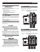
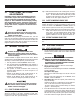

Table Of Contents

2
1.1 INTRODUCTION
This manual has been prepared especially for the purpose of famil-
iarizing personnel with the design, application, installation, opera-
tion and servicing of the applicable equipment. Read the manual
carefully and comply with all instructions. This will help to prevent
accidents or damage to equipment that might otherwise be caused
by carelessness, incorrect application, or improper procedures.
Every effort has been expended to make sure that the contents
of this manual are both accurate and current. The manufacturer,
however, reserves the right to change, alter or otherwise improve
the product at any time without prior notice.
1.2 EQUIPMENT DESCRIPTION
The automatic transfer switch is used for transferring critical
electrical loads from a UTILITY (NORMAL) power source to an
EMERGENCY (GNERATOR) power source.
The transfer switch prevents electrical feedback between the
UTILITY and EMERGENCY sources. For that reason, electrical
codes require a transfer switch in all standby electric system
installations.
When the transfer switch is connected to the engine generator
control panel, the control panel constantly monitors the UTILITY
voltage and controls the operation of the transfer switch.
Should the UTILITY voltage drop below a preset value, and remain
at this low voltage for a preset amount of time, the generator
cranks and starts. After the generator starts, the transfer switch
transfers the load circuits to the generator, the generator then sup-
plies the loads. When UTILITY returns above a preset level the load
is transferred back to the UTILITY and the generator shuts down.
1.3 TRANSFER SWITCH DATA
LABEL
A DATA LABEL is permanently affixed to the transfer switch enclo-
sure. Use this transfer switch only with the specific limits shown
on the DATA LABEL and on other decals and labels that may be
affixed to the switch. This will prevent damage to equipment and
property.
When requesting information or ordering parts for this equipment,
make sure to include all information from the DATA LABEL.
Record the Model and Serial numbers in the space provided below
for future reference.
MODEL #
SERIAL #
1.4 TRANSFER SWITCH
ENCLOSURE
The standard switch enclosure is a National Electrical Manufacturer’s
Association (NEMA) and UL 3R type. UL and NEMA 3R type enclo-
sures primarily provide a degree of protection against falling rain
and sleet; undamaged by the formation of ice on the enclosure.
1.5 SAFE USE OF TRANSFER
SWITCH
Before installing, operating or servicing this equipment, read the
SAFETY RULES (inside front cover) carefully. Comply strictly with
all SAFETY RULES to prevent accidents and/or damage to the
equipment. The manufacturer recommends a copy of the SAFETY
RULES are made and posted near the transfer switch. Also, be
sure to read all instructions and information found on tags, labels
and decals affixed to the equipment.
Two publications that outline the safe use of transfer switches are
the following:
NFPA 70; National Electrical Code•
UL 1008, STANDARD FOR SAFETY-AUTOMATIC TRANSFER •
SWITCHES
NOTE:
It is essential to use the latest version of any standard to ensure
correct and current information.
General Information