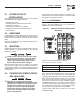
RTS Automatic Transfer Switch TECHNICAL MANUAL A new standard of reliability This manual should remain with the unit.
Important Safety Instructions and information on tags, decals, and labels that may be affixed to the transfer switch. Replace any decal or instructions label that is no longer legible. Read the following information carefully before attempting to install, operate or service this equipment.
Table of Contents • Keep the transfer switch enclosure door closed and bolted at all times. Only qualified personnel should be permitted access to the switch interior. • In case of an accident caused by electric shock, immediately shut down the source of electrical power. If this is not possible, attempt to free the victim from the live conductor but AVOID DIRECT CONTACT WITH THE VICTIM. Use a nonconducting implement, such as a rope or board, to free the victim from the live conductor.
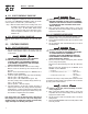
Section 1 — General Information RTS “W” Type Transfer Switch 1.1 INTRODUCTION This manual has been prepared especially for the purpose of familiarizing personnel with the design, application, installation, operation and servicing of the applicable equipment. Read the manual carefully and comply with all instructions. This will help to prevent accidents or damage to equipment that might otherwise be caused by carelessness, incorrect application, or improper procedures.
Section 2 — Installation RTS “W” Type Transfer Switch 2.1 INTRODUCTION TO INSTALLATION This equipment has been wired and tested at the factory. Installing the switch includes the following procedures: • • • • • • Mounting the enclosure. Connecting utility and generator power source leads. Connecting the load leads. Connecting any auxiliary contact (if needed) Installing/connecting any options and accessories. Testing functions. 2.2 Wiring diagrams and electrical schematics are provided in this manual.
Section 3 — Operation RTS “W” Type Transfer Switch NOTE: Use a torque wrench to tighten the conductors, being sure not to overtighten, or damage to the switch base could occur. If undertightened, a loose connection would result, causing excess heat which could damage the switch base. Connect power source load conductors to clearly marked transfer mechanism terminal lugs as follows Connect UTILITY (NORMAL) power source cables to switch terminals N1, N2, N3. 2.
Section 3 — Operation RTS “W” Type Transfer Switch 3.2 MANUAL OPERATION DANGER NOT manually transfer under load. Do Disconnect transfer switch from all power sources by approved means, such as a main circuit breaker(s). A manual HANDLE is shipped with the transfer switch. Manual operation must be checked BEFORE the transfer switch is operated electrically. To check manual operation, proceed as follows: 1. 2. Turn the generator’s AUTO/OFF/MANUAL switch to OFF.
Section 3 — Operation RTS “W” Type Transfer Switch 3.2.2 CLOSE TO EMERGENCY SOURCE SIDE Before proceeding, verify the position of the switch by observing window “B” in Figure 3.1. If window “B” reads “ON”, the contacts are closed in the EMERGENCY (STANDBY) position. No further action is required. If it reads “OFF”, proceed with Step 1. • Step 1: With the handle attached to the actuating shaft, move the handle in the direction of the arrow on the switch cover until it stops - DO NOT FORCE.
Section 3 — Operation RTS “W” Type Transfer Switch NOTE: Do NOT proceed until generator AC output voltage and frequency are correct and within stated limits. If the no-load voltage is correct but no-load frequency is incorrect, the engine governed speed probably requires adjustment. If no-load frequency is correct but voltage is not, the voltage regulator may require adjustment. 3.4 1. 2. 3. 4. GENERATOR TESTS UNDER LOAD Set the generator's main circuit breaker to its OFF or OPEN position.
Section 4 — Notes RTS “W” Type Transfer Switch 8
Section 4 — Notes RTS “W” Type Transfer Switch 9
10 TRIPLE EKO SUITABLE FOR 1", 1.25" & 1.50" CONDUIT 3 PLACES 179.5mm[7.1"] 613mm[24.1"] 513.04mm[20.2"] MOUNTING HOLES: Ø6.35mm[Ø0.25"] 4-PLACES 430mm[16.9"] 61.5mm[2.4"] 490mm[19.3"] 41.5mm[1.6"] Section 5 — Mounting Dimensions RTS “W” Type Transfer Switch Mounting Dimensions - 100/200A 208V – Drawing No.
TRIPLE EKO SUITABLE FOR 1", 1.25" & 1.50" CONDUIT 3 PLACES 254mm[10.0"] 917mm[36.1"] 609.6mm[24.0"] 487mm[19.2"] MOUNTING HOLES: Ø6.35mm[Ø0.25"] 4-PLACES 60.8mm[2.4"] 794mm[31.3"] 61.3mm[2.4"] Section 5 — Mounting Dimensions Mounting Dimensions - 100A 480V – Drawing No.
12 TRIPLE EKO SUITABLE FOR 1", 1.25" & 1.50" CONDUIT 3 PLACES 332mm[13.1"] 1220.9mm[48.1"] 765.8mm[30.1"] MOUNTING HOLES: Ø6.35mm[Ø0.25"] 4-PLACES 635mm[25.0"] 63.5mm[2.5"] 1092mm[43.0"] 65.39mm[2.6"] Section 5 — Mounting Dimensions RTS “W” Type Transfer Switch Mounting Dimensions - 200A 480V – Drawing No.
TB1 CUSTOMER CONNECTION 8 7 RM STRT WIRE 178 6 RM STRT WIRE 183 5 TRNS SW WIRE 194 4 TRNS SW WIRE 23 3 UTILITY N2 2 UTILITY N1 1 E2 (E3) NOTE: E3, N3 AND T3 WIRES ARE ONLY USED ON 3 PHASE SYSTEMS E1 E2 NEUTRAL BLOCK E1 POWER LEADS AND TRANSFER SWITCH LEADS MUST BE RUN IN TWO DIFFERENT CONDUITS.
Section 6 — Electrical Data RTS “W” Type Transfer Switch Wiring Diagram/Schematic 100/200A, 208V – Drawing No.
Section 6 — Electrical Data RTS “W” Type Transfer Switch Wiring Diagram/Schematic 100/200A, 208V – Drawing No.
Section 6 — Electrical Data RTS “W” Type Transfer Switch Wiring Diagram/Schematic 100/200A, 480V – Drawing No.
Section 6 — Electrical Data RTS “W” Type Transfer Switch Wiring Diagram/Schematic 100/200A, 480V – Drawing No.
Section 7 — Exploded Views and Parts List RTS “W” Type Transfer Switch 100 A, 208V, 3-pole Switch Assembly – Drawing No.
Section 7 — Exploded Views and Parts List RTS “W” Type Transfer Switch 100 A, 208V, 3-pole Switch Assembly – Drawing No. 0F5582$-G ITEM PART NO. QTY.
Section 7 — Exploded Views and Parts List RTS “W” Type Transfer Switch 200A, 208V, 3-pole Switch Assembly – Drawing No.
Section 7 — Exploded Views and Parts List RTS “W” Type Transfer Switch 200A, 208V, 3-pole Switch Assembly – Drawing No. 0E4312$-M ITEM PART NO. QTY.
Section 7 — Exploded Views and Parts List RTS “W” Type Transfer Switch 100A, 480V, 3-pole Switch Assembly – Drawing No.
Section 7 — Exploded Views and Parts List RTS “W” Type Transfer Switch 100A, 480V, 3-pole Switch Assembly – Drawing No. 0F6101$-F ITEM PART NO. QTY.
Section 7 — Exploded Views and Parts List RTS “W” Type Transfer Switch 200A, 480V, 3-pole Switch Assembly – Drawing No.
Section 7 — Exploded Views and Parts List RTS “W” Type Transfer Switch 200A, 480V, 3-pole Switch Assembly – Drawing No. 0H1569$-A ITEM PART NO. QTY.
Section 8 — Warranty RTS “W” Type Transfer Switch GENERAC POWER SYSTEMS STANDARD TWO-YEAR LIMITED WARRANTY FOR GENERAC TRANSFER SWITCH SYSTEMS NOTE: ALL UNITS MUST HAVE A START-UP INSPECTION PERFORMED BY AN AUTHORIZED GENERAC DEALER. For a period of two (2) years or two thousand (2,000) hours of operation from the date of sale, which ever occurs first, Generac Power Systems, Inc.