
Product Manual


4
Use a torque wrench to tighten the conductors,
being sure not to overtighten, or damage to the
switch base could occur. If undertightened, a
loose connection would result, causing excess
heat which could damage the switch base.
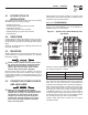
Connect power source load conductors to clearly marked transfer
mechanism terminal lugs as follows
1. Connect UTILITY (NORMAL) power source cables to switch
terminals N1, N2, N3.
2. Connect EMERGENCY (STANDBY) source power cables to
transfer switch terminals E1, E2, E3.
3. Connect customer LOAD leads to switch terminals T1, T2,
T3.
4. Connect neutral conductors of UTILITY, EMERGENCY and
customer LOAD to the neutral block.
Conductors must be properly supported, of approved insulative
qualities, protected by approved conduit, and of the correct wire
gauge size in accordance with applicable codes.
Be sure to maintain proper electrical clearance between live metal
parts and grounded metal. Allow at least 1/2 inch for 100-400
amp circuits.
2.5 CONNECTING START CIRCUIT
WIRES
Control system interconnections consist of UTILITY 1 and 2, and
leads 23 and 194. Control system interconnection leads must
be run in a conduit that is separate from the AC power lead.
Recommended wire gauge sizes for this wiring depends on the
length of the wire, as recommended below:
MAXIMUM WIRE LENGTH RECOMMENDED WIRE SIZE
460 feet (140m) No. 18 AWG.
461 to 730 feet (223m) No. 16 AWG.
731 to 1,160 feet (354m) No. 14 AWG.
1,161 to 1,850 feet (565m) No. 12 AWG.
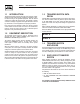
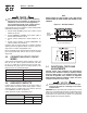
2.6 AUXILIARY CONTACTS
If desired, there are Auxiliary Contacts on the transfer switch to
operate customer accessories, remote advisory lights, or remote
annunciator devices. A suitable power source must be connected
to the COMMON (C) terminal. See Figure 2.2.
Contact operation is shown in the following chart:
Switch Position
Utility Standby
Common to Normally Open Open Closed
Common to Normally Closed Closed Open
NOTE:
Auxiliary Contacts are rated 10 amps at 125 or 250 volts AC.
DO NOT EXCEED THE RATED VOLTAGE AND CURRENT OF THE
CONTACTS.
Figure 2.2 – Auxiliary Contacts
Optional
Auxiliary Contact
(Actuated)
Side views shown in Utility position
3.1 FUNCTIONAL TESTS AND
ADJUSTMENTS
Following transfer switch installation and interconnection,
inspect the entire installation carefully. A competent, qualified
electrician should inspect it. The installation should comply
strictly with all applicable codes, standards, and regulations.
When absolutely certain the installation is proper and correct,
complete a functional test of the system.
Perform functional tests in the exact order pre-
sented in this manual, or damage to the switch
could be done.
IMPORTANT: Before proceeding with functional tests, read and
make sure you understand all instructions and information in this
section. Also read the information and instructions of labels and
decals affixed to the switch. Note any options or accessories that
might be installed and review their operation.
Section 3 — Operation
RTS “W” Type Transfer Switch