
Installation Guide

Electrical System
Installation Guidelines For Spark-Ignited Stationary Generators 33
NOTE: The following table is provided for reference pur-
poses only. See latest NEC, state, and local AHJ require-
ments for correct sizing.
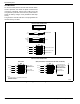
Optional Accessory Power
• Accessory power for optional items (battery
warmer and block heater) should come from a cus
-
tomer utility supply source (with appropriate sized
breaker), which is also powered by emergency
power during an outage.
• Optional user installed GFCI receptacles. Provides
a place to plug in optional battery warmer and
block heater.
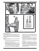
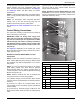
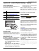
NOTE: See Figure 5-2. Remove knockout plug and
route accessory wiring to customer supplied weather-
proof junction box. Verify wires do not contact moving or
vibrating engine parts, as abraded wires can result in
electrical problems.
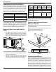
Installing Stub-Up Cover and Rear
Panel
1. Install five screws with flat washers to secure stub-
up cover.
2. Install four screws with nylon washers to fasten
fascia over control panel.
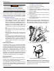
3. Install rear panel. For best results, first engage
right side of panel and then rotate left side inward
toward enclosure. Alternately work left and right
sides in until slots are aligned with screw holes on
both sides. Install six screws with nylon washers
and tighten until snug.
Transfer Switch Location
The location of the transfer switch is important. Consider
the following:
• Locate transfer switch as close to emergency load
as practical, to avoid interruptions of emergency
power system due to natural disasters or equip
-
ment failures.
• Locate transfer switch in a clean, dry, well venti-
lated location, away from excessive heat. Allow
adequate working space around transfer switch.
See latest NEC, state, and local AHJ requirements
for details.
• Install power and control wires as per NEC require-
ments. In a three-phase system, all power conduits
from the generator must contain all three phases.
• Conduit, wire, circuit protective device sizes, insu-
lation, etc. must conform to applicable local and
national codes and regulations.
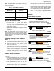
Battery
General Safety Precautions
Table 5-2. Control Wire Length/Size
Maximum
Wire Length
Recommended
Wire Size
1–115 ft (0.30–35 m) No. 18 AWG
116–185 ft (36–56 m) No. 16 AWG
186–295 ft (57–89 m) No. 14 AWG
296–460 ft (90–140 m) No. 12 AWG
Automatic start-up. Disconnect utility power and
render unit inoperable before working on unit.
Failure to do so will result in death or serious injury.
(000191)
DANGER
(000188)
DANGER
Electrocution. Do not wear jewelry while
working on this equipment. Doing so will
result in death or serious injury.
(000130)
WARNING
Accidental Start-up. Disconnect the negative battery
cable, then the positive battery cable when working
on unit. Failure to do so could result in death
or serious injury.
(000137a)
WARNING
Explosion. Batteries emit explosive gases while
charging. Keep fire and spark away. Wear protective
gear when working with batteries. Failure to do so
could result in death or serious injury.
(000138a)
WARNING
Risk of burns. Batteries contain sulfuric acid and can
cause severe chemical burns. Wear protective gear
when working with batteries. Failure to do so could
result in death or serious injury.
(000133)
WARNING
Explosion. Batteries emit explosive gases.
Always connect positive battery cable first to
avoid spark. Failure to do so could result in
death or serious injury.