
Installation Guide

Gaseous Fuel Systems
Installation Guidelines For Spark-Ignited Stationary Generators 27
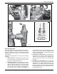
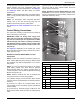
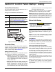
Figure 4-5. Fuel Pressure Test Points
Final Test Procedure
The following test must be performed at startup to docu-
ment and validate fuel system operation. It requires a
load bank connected to the unit, or a combination of load
bank and system load, to bring unit to its full rated kW
load capacity.
Measure fuel supply pressure under each of the following
conditions:
1. Static Pressure: Fuel supply pressure when unit is
not running. Must not exceed maximum pressure
listed in the unit specification sheet.
2. Cranking Pressure: Fuel supply pressure when
unit is cranking. Must not drop more than 1 in water
column (0.25 kPa) below Static Pressure or below
minimum pressure listed in the unit specification
sheet. If it does, it may indicate fuel supply piping is
not correctly sized, or primary fuel regulator is
incorrectly sized, or mounted too close to the gen
-
erator connection point. Unit may experience hard
starting, or will not perform as expected at full load
or during load transients.
3. Running—No Load Pressure: Fuel supply pres-
sure when unit is running at rated frequency and
voltage with no load. Must be at or slightly below
maximum pressure as listed in the unit specifica
-
tion sheet.
4. Running—Full Load Pressure: Fuel supply pres-
sure when unit is running with full rated load
applied (kW). Fuel supply pressure should not drop
more than 1–2 in water column (0.25–0.50 kPa)
from the Running—No Load Pressure and must
NEVER drop below minimum pressure listed in the
unit specification sheet.
A
B
C
Gauge Adapter
1/8 Inch Diameter Probe
Part No. 0K2341
009107