
Use and Care Manual


Activation and Startup
16 Owner’s Manual for Spark-Ignited Stationary Generators
13. Allow engine to run at no-load for 2–5 minutes.
14. Pr
ess OFF on control panel to shut engine down. A
red LED illuminates to verify system is OFF.
Testing Auxiliary Shutdown Switch Operation
The generator is equipped with an independent means of
shutting down prime mover (engine) for use in emer-
gency situations. The shutdown mechanism, when acti-
vated, requires a mechanical reset.
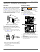
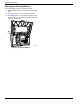
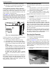
See Figure 3-6. Generators 15 kW and larger are
equipped with two auxiliary shutdown switches. One aux-
iliary shutdown switch (A) is located
on the generator roof
above and to the right of the viewing window. The second
auxiliary shutdown switch (B) is inside the control panel
enclosure.
004900
ON
OFF
ENGINE
SHUTDOWN
004890
A
B
Figure 3-6. Auxiliary Shutdown Switches
Proceed as follows to test auxiliary shutdown switches
a
fter installation to verify correct operation:
1. V
erify auxiliary shutdown switches are ON (I).
2. Pr
ess MANUAL on control panel to start engine.
3. With
engine running, set one auxiliary shutdown
switch to OFF (O). Engine should shut down imme-
diately.
• If
engine stops, set auxiliary shutdown switch to
ON (I), clear alarm on controller, and restart engine
to verify generator is operating normally. After veri-
fying normal operation of firs
t auxiliary switch, ver-
ify operation of second aux
iliary switch.
• If
engine does not stop, auxiliary shutdown
switch is not functioning correctly. Contact an
IASD.
NOTE: Auxiliary
shutdown switches are not intended to
be a primary means to shut down generator under nor-
mal operating conditions. Accid
ental activation of an aux-
iliary shutdown switch will prevent
generator from
operating during a power outage.
Checking Automatic Operation
Proceed as follows to check system for correct automatic
operation:
1. V
erify generator is in OFF mode. A red LED on
control panel illuminates to verify system is OFF.
2. Inst
all front cover of transfer switch.
3. T
urn on utility power supply to transfer switch,
using the means provided (such as a utility MLCB).
NOTE: T
ransfer switch will transfer to UTILITY.
4. Set
generator MLCB (generator disconnect) to ON
(CLOSED).
5. Pre
ss AUTO on control panel. The system is now
ready for automatic operation.
6. T
urn off utility power supply to transfer switch.
With generator ready for automatic
operation, engine will
crank and start when utility source power is turned off
after a 10 second delay (factory default setting). After
starting, transfer switch connects load circuits to standby
side. Allow system to operate through its entire automatic
sequence of operation.
With generator running and loads powered by generator
AC
output, turn on utility power supply to transfer switch.
The system transfers back to utility position and then
runs through cool down cycle and shuts down.
Securing the Generator
Proceed as follows to secure the generator:
1. Us
e key to install side access panels.
2. Close viewing window
.
NOTE: See Figure 3-7. Obtain viewing window hasp, if
not installed. With retaining tab at the bottom, insert
squ
are end of viewing window hasp into slot below view-
ing window. Push on viewing window hasp until it snaps
in
place. Gently pull on viewing window hasp to verify it
will not come free.
3. Insta
ll customer supplied padlock into viewing win-
dow hasp.
006376
Figure 3-7. Install Viewing Window Hasp