
Use and Care Manual

Owner’s Manual for Spark-Ignited Stationary Generators 11
Activation and Startup
Section 3: Activation and Startup
Orientation
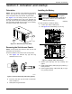
NOTE: The 4.5L (48 kW) unit is depicted in the artwork
used in this manual. The location and appearance of
some components may vary between engine models.
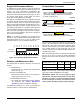
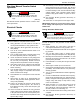
See Figure 3-1. The viewing window (A) side of the
enclosure is identified as the rear of the generator set.
Th
e right and left sides are identified by standing at the
rear and looking towards the front of the unit. The battery
is located on the left side of the unit (B).
009676
A
B
Figure 3-1. Enclosure (Rear Left View)
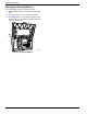
Removing the Side Access Panels
NOTE: Access panels are located at both the left and
right sides of the enclosure.
Proceed as follows to remove the side access panels:
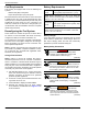
1. See Figure 3-2. Remove key (B) from bag
attached to door of unit.
010077
B
A
Figure 3-2. Access Panel Key and Latch (Typical)
2. Inser
t key into latch (A) and rotate counterclock-
wise one half turn.
3. Raise pa
nel using thumb latch.
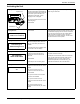
Installing the Battery
(000133)
WARNING
Explosion. Batteries emit explosive gases.
Always connect positive battery cable first to
avoid spark. Failure to do so could result in
death or serious injury.
Proceed as follows to install the battery:
1. Lo
osen nylon strap on battery tray.
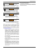
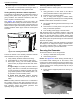
2. See Figure 3-3. Install battery (C) onto tray.
010078
B
A
B
C
A
D
Figure 3-3. Battery Cable Connections
3. Secur
e nylon strap (D) over top of battery and
tighten.
4. In
stall positive battery cable (red) (A) to positive (+)
battery terminal.
5. Insta
ll negative battery cable (black) (B) to nega-
tive (-) battery terminal.