
Use and Care Manual

General Information
6 Owner’s Manual for Spark-Ignited Stationary Generators
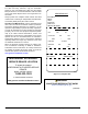
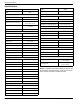
Specifications
Model 48 kW
Engine
4.5L
Class F
Class H
83.4 x 35.0 x 45.1
(21
1.8 x 88.9 x 114.6)
1,781 (808)
1,893 (859)
In-line
710 (322)
4.5 / 114.3
4.25 / 107.95
4.43L
1-3-4-2
CW from flywheel
9.9:1
0.31–0.45
1,800
Belt driven
2,100
20/508
Pusher
2,829
2.9 / 11
201,060
150 °F (60 °C)
140 °F (50 °C)
194 °F (90 °C)
Gear
Full flow spin-on cartridge
12 / 11.36
Citgo Citgard® 5W-20
Naturally aspirated
Closed
104 scfm (10.6 cmm)
945 °F (507 °C)
12V, 35 amp
Group 27F, 725 CCA
2.5 Amp
Electronic
Isochronous
± 0.25%
Electronic
Single-phase
± 1%
5–14 in water column
(1.24–3.48 kPa)
3.5–14 in water column
(
0.87–3.48 kPa)
NOTE: A complete specification sheet is included in the
documentation provided with the unit at the time of pur-
chase. Contact an IASD for additional copies.
Generator Set
Rotor insulation
Stator insulation
Dimensions L x W x H—in (cm)
Product weight—lbs (kg)
Shipping weight—lbs (kg)
Engine System
Ty
pe
Dry weight—lbs (kg)
Bore (in/mm)
Stroke (in/mm)
Displacement (L)
Firing order
Direction or rotation
Compression ratio
Spark plug gap (mm)
Rated synchronous rpm
Cooling System
Wa
ter pump
Fan speed (rpm)
Fan diameter (in/cm)
Fan Mode
Air Flow (ft
3
/min)
Coolant capacity (gal/L)
Heat rejection to coolant (Btu/h)
Max operating air temp on radiator
Max ambient temp
Thermostat (full open)
Lubricating System
Oil pump type
Oil filter type
Crankcase oil capacity (qts/L)
Lubricating oil type
Air Intake System
Type
Exhaust System
Breath
er
Exhaust flow at rated output 60 Hz
Exhaust temperature at rated output
Electrical System
Batter
y charge alternator
Recommended battery
Static battery charger
Governor System
Ty
pe
Frequency regulation
Steady state regulation
Voltage Regulator
Ty
pe
Sensing phase
Regulation
Fuel System
LP
fuel pressure
NG fuel pressure
Model 48 kW
Eng
ine 4.5L