Serial Number QT 5.4L 100kW Models STANDBY GENERATOR OWNER'S MANUAL A new standard of reliability This manual should remain with the unit. Cover008 Rev. 0 08/05 Part No.
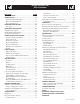
Standby Generator Sets Table of Contents SECTION PAGE SAFETY RULES ................................................ 1-1 Fuel System ..............................................................8-1 Generator Set Lubrication ........................................8-1 INTRODUCTION .....................................................1-3 Prior to Initial Start-up .............................................8-1 Read this Manual Thoroughly ...................................
Standby Generator Sets Important Safety Instructions WARNING: GENERAL HAZARDS • For safety reasons, the manufacturer recommends that this equipment be installed, serviced and repaired by an Authorized Service Dealer or other competent, qualified electrician or installation technician who is familiar with applicable codes, standards and regulations. The operator also must comply with all such codes, standards and regulations.
Standby Generator Sets Important Safety Instructions • Generators installed with an automatic transfer switch will crank and start automatically when normal (utility) source voltage is removed or is below an acceptable preset level. To prevent such automatic start-up and possible injury to personnel, disable the generator’s automatic start circuit (battery cables, etc.) before working on or around the unit. Then, place a “Do Not Operate” tag on the generator control panel and on the transfer switch.
Standby Generator Sets Important Safety Instructions INTRODUCTION This symbol points out potential fire hazard. symbol points out potential electrical shock This hazard. Thank you for purchasing this model of the standby generator set product line. Every effort was expended to make sure that the information and instructions in this manual were both accurate and current at the time the manual was written.
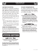
Standby Generator Sets General Information IDENTIFICATION RECORD Identification Code DATA LABEL Use this code to obtain important information about the generator. For example, if the code is: Every generator set has a DATA LABEL that contains important information pertinent to the generator. The data label, which can be found attached to the generator’s lower connection box, lists the unit’s serial number and its rated voltage, amps, wattage capacity, phase, frequency, rpm, power factor, etc.
Standby Generator Sets Equipment Description EQUIPMENT DESCRIPTION COOLANT RECOMMENDATIONS This equipment is a revolving field, alternating current generator set. It is powered by a gaseous fueled engine operating at 1800 rpm for 4-pole direct drive units, 3600 rpm for 2-pole direct drive units and 2300 - 3000 rpm for quiet drive gear units. See the Specifications section for exact numbers.
Standby Generator Sets Engine Protective Devices OIL PRESSURE SENSING ENGINE PROTECTIVE DEVICES The standby generator may be required to operate for long periods of time without an operator on hand to monitor such engine conditions as coolant temperature, oil pressure or rpm.
Standby Generator Sets Fuel Systems FUEL SYSTEM PROPANE VAPOR WITHDRAWAL FUEL SYSTEM FUEL REQUIREMENTS This type of system utilizes the vapors formed above the liquid fuel in the supply tank. Approximately 10 to 20 percent of the tank capacity is needed for fuel expansion from the liquid to the vapor state. The vapor withdrawal system is generally best suited for smaller engines that require less fuel.
Standby Generator Sets Specifications SPECIFICATIONS Engine Lubrication System Type of Oil Pump ...................................................................... Gear Oil Filter .............................................................Full Flow, Cartridge Crankcase Oil Capacity ....................................................5 U.S. qts. GENERATOR Type ............................................................................. Synchronous Rotor Insulation .................................
Standby Generator Sets Specifications Figure 1 — Interconnections GROUND ONLY AT GENERATOR BOX COLD WEATHER KIT For cold climates, optional cold weather kit (part number 0F6148A) is recommended. The kit includes: • • • • Battery Warmer 4” Junction Box with hardware Thermostat; 20 deg “ON”, 40 deg “OFF” 6 qt. pack 5W-30 synthetic oil (engine) 6-2 GenSpec007 Rev.
Standby Generator Sets Specifications 5.4L & 6.8L IGNITION DESCRIPTION NOTE: This single-fire Ignition is intended to operate with a 10-cylinder, 6.8L engine and an 8-cylinder, 5.4L engine. The ignition cover does not need to be removed to see the LED. The 6.8L engine uses a 40-1 crank sensor, a magpickup CAM sensor and individual coil-on-plug coils for each spark-plug.
Standby Generator Sets General Information GENERATOR AC LEAD CONNECTIONS ALTERNATOR POWER WINDING CONNECTIONS See “Voltage Codes”. This generator may be rated at any one of three voltages, either single-phase or three-phase. The electrical wires in the unit’s AC connection (lower) panel should be installed according to the number of leads and the voltage/phase required for the application. If there are any questions regarding lead connection, refer to the wiring diagrams at the back of this manual.
Standby Generator Sets Installation PRIOR TO INITIAL START-UP INSTALLATION Refer to the separate “Installation Guide QT Product Line” supplied with the unit. to initially starting the generator, it must Prior be properly prepared for use. Any attempt to PREPARATION BEFORE START-UP The instructions in this section assume that the standby generator has been properly installed, serviced, tested, adjusted and otherwise prepared for use by a competent, qualified installation contractor.
Standby Generator Sets Installation START-UP CHECKLIST • Check voltage at the generator terminals. • For 3-phase units, check phase rotation at the transfer switch terminals. The generator phase rotation must match the utility phase rotation. • Check for coolant, fuel, oil, and exhaust leaks. • Close the generators main line circuit breaker. • Turn the generator set off. • Connect the UTILITY supply to the transfer switch. • Set the AUTO/OFF/MANUAL switch to AUTO.
Standby Generator Sets Operation GENERATOR CONTROL AND OPERATION not crank the engine continuously for longer Do than 30 seconds, or the heat may Refer to the appropriate control panel operator’s manual for this unit. • • OPERATING UNIT WITH MANUAL TRANSFER SWITCH If the generator was installed in conjunction with a transfer switch capable of manual operation only, the following procedure applies.
Standby Generator Sets Maintenance MAINTENANCE PERFORMED BY AUTHORIZED SERVICE FACILITIES exhaust system parts from this product get The extremely hot and remain hot after shutdown. High grass, weeds, brush, leaves, etc. must remain clear of the exhaust. Such materials may ignite and burn from the heat of the exhaust system. Before working on the generator, ensure the following: • The AUTO/OFF/MANUAL switch is in the OFF position. • The 15A fuse has been removed from the control box.
Standby Generator Sets Maintenance ENGINE COOLANT CHECK FAN BELT Check coolant level in coolant recovery bottle. See the “Specifications” section. • Inspect fan belts every three months. Replace any damaged, deteriorated, worn or otherwise defective belt. • Check fan belt tension. Thumb pressure, exerted midway between pulleys, should deflect about 3/8 to 5/8 inch. Adjust belt tension as required. • Add recommended coolant mixture as necessary.
Standby Generator Sets Maintenance SPARK PLUGS 7. Start engine and check for oil leaks. Reset the spark plug gap or replace the spark plugs as necessary. Figure 10.2 - Oil Filter 1. Clean the area around the base of the spark plugs to keep dirt and debris out of the engine. Clean by scraping or washing using a wire brush and commercial solvent. Do not blast the spark plugs to clean. 2. Remove the spark plugs and check the condition. Replace the spark plugs if worn or if reuse is questionable.
Standby Generator Sets Maintenance Finally, have the insulation resistance of stator and rotor windings checked. If insulation resistances are excessively low, the generator may require drying. DANGER batteries give off explosive hydrogen Storage gas. This gas can form an explosive mixture BATTERY around the battery for several hours after charging. The slightest spark can ignite the gas and cause an explosion. Such an explosion can shatter the battery and cause blindness or other injury.
Standby Generator Sets Service Schedule SERVICE SCHEDULE 30 KW - 150 KW STANDBY GAS ENGINE DRIVEN GENERATOR SETS The following is a recommended maintenance schedule for standby gas engine driven generator sets from 30kW to 150 kW in size. The established intervals in the schedule are the maximum recommended when the unit is used in an average service application. They will need to be decreased (performed more frequently) if the unit is used in a severe application.
Standby Generator Sets Service Schedule Maintenance Tasks Level 1 Recommended to be done monthly/ 10 hrs. Level 2 Level 3 Task Required Task Required Comp. to be done Comp. to be done (Date- 3 months/ (DateSemiInitials) Break-in Initials) annually/ 30 hrs. 50 hrs. 1. Disable the unit from operating per the first page warning. 2. Check the engine oil level. Adjust as necessary. 3. Check the engine coolant level. Adjust as necessary. 4. Check the engine coolant thermal protection level.
Standby Generator Sets Service Schedule Maintenance Tasks Level 1 Recommended to be done monthly/ 10 hrs. Level 2 Level 3 Task Required Task Required Comp. to be done Comp. to be done (Date- 3 months/ (DateSemiInitials) Break-in Initials) annually/ 30 hrs. 50 hrs. Level 4 Task Comp. (DateInitials) Required to be done Annually/ 100 hrs. Level5 Task Comp. (DateInitials) Required to be done Biannually/ 250 hrs. Task Comp. (DateInitials) 10.
Standby Generator Sets Service Schedule Maintenance Tasks Level 1 Recommended to be done monthly/ 10 hrs. Level 2 Level 3 Task Required Task Required Comp. to be done Comp. to be done (Date- 3 months/ (DateSemiInitials) Break-in Initials) annually/ 30 hrs. 50 hrs. 18. Start and exercise the unit at full rated load (use a load bank if the site load is not enough) for at least 2 hours looking for leaks, loose connections or components, and abnormal operating conditions. Correct as necessary. 19.
Standby Generator Sets Troubleshooting TROUBLESHOOTING GUIDE PROBLEM CAUSE CORRECTION Engine won’t crank. 1. 15 amp fuse blown. 2. Loose or corroded or defective battery cables. 3. Defective starter contactor. 4. Defective starter motor. 5. Dead or Defective Battery. 6. 5 amp fuse blown. 1. Replace fuse. 2. Tighten, clean or replace battery cables as necessary. 3. Replace contactor.* 4. Replace starter motor.* 5. Remove, change or replace battery. 6. Replace fuse.* Engine cranks but won't start 1.
Standby Generator Sets Notes
Standby Generator Sets Notes
1 2 3 4 5 6 7 8 9 10 11 12 13 14 15 0F9952 0F3417 0F2984 0F9949 0F3418 0F2985 0F9950 0F9951 0F6183 0F6187 0F6184 0F6212 068405C 0F3013 072878 0C9708 0F3726B 0F2689 023454 0F8408 046526 0A2601 0A2602 022473 022097 1 1 1 1 1 1 1 1 1 1 1 1 1 1 1 REF 1 1 1 4 4 1 1 8/12 4/6 ASSY ROTOR 2390 80KB3 CPL ASSY ROTOR 390 2P 100K BRSHLS ASSY ROTOR 390 2P 150K BRSHLS ASSY STATOR 80KW 1PH 2P BRSHLS ASSY STATOR 390 2P 100K BRSHLS ASSY STATOR 390 2P 150K BRSHLS UL STATOR 2390 80 GB3 CPL STATOR 2390 80 KB3 CPL ASSY STR 3
1 2 0F2885 0F2883 0F9637 (4) 1 1 1 3 4 0F3685 023484N 023484N 1 1 2 5 086961 067617030A 067617030B 043180 022264 0C3990 057701 022155 0C2428 0F3618 0A9457 057073 0D5466 0A7822 022237 022241 049226 0C2266 0C2454 042568 022473 022097 049813 0D4698 0F4464 025433 024469 067210A 0D6029 051713 081008 077043J 077043J 1 4 4 4 REF. 2 2 1 1 2 REF. REF.
3.) A B C D E F G H J K L M N P R S T U V (1) W 4.
1 2 3 4 5 6 7 8 9* 10 11 12 13 14 15 ** 16 ** 17 18 19 20 21 22 23 24 25 26 * 27 28 29 30 31 32 33 34 35 0F2885 0G0171 0G0171A 0G0172 023484N 0F4677 067617030A 067617030B 043180 022264 0C3990 057701 022155 0C2428 0F3618 0A9457 057073 0D5466 0A7822 022237 022241 049226 0C2266 0C2454 042568 022473 022097 049813 0D4698 0F4464 025433 024469 067210A 0D6029 051713 081008 077043J 0F6156 1 1 1 1 1 1 4 4 4 REF. 2 2 1 1 2 REF. REF.
1 2 3 4 5 6 7 8 9 10 11 12 13 14 15 16 17 18 19 20 21 22 23 24 25 26 27 28 29 30 31 32 33 34 35 36 39 40 42 43 44 45 46 47 48 * 49 50 51 52 53 54 55 56 57 58 59 60 61 0F2687 0F2611 0F5254 0F5253 0F7077 046526 051756 0C2454 052250 076749 0F2573 0F2610 0F2572 0F5689 0F2862 0F2560 022131 039414 052625 0F2561 0C8165 0D6795 0C7043 0E8909 048031C 0C8146 082774 0F2686 0F5463 0F8695 0F4028 0F4030 0F4032 0F4496 042911 0F2872 022304 022195 022196 049813 049820 022145 022129 035685 045764 065852 0C7649 055596 069860
1 2 3 4 5 6 7 8 9 10 11 12 13 14 15 16 17 18 19 20 21 22 23 24 25 26 0F3099 065852 052252 052257 052259 055597 052251A 052860 0F2895 045764 022447 061383 043107 022473 049813 057192 022131 046526 0536210360 042909 022261 022129 022145 045771 038750 022097 1 1 5 5 5 5 5 4 2 1 1 1 1 1 1 8 8 8 1 1 2 1 2 2 1 1 MTG BASE CP 5.4L 100KW DD SPRING CLIP HOLDER .37-.62 DAMPENER VIBRATION SPACER .49 X .62 X 1.87 PWDR/ZINC WASHER FLAT M12 SCREW HHC M12-1.75 X 85 G8.8 DAMPENER VIBRATION 50 WHITE NUT LOCKING M12-1.
1 2 3 4 5 6 7 8 9 10 11 12 13 14 0F3408 0F3411 058208 022131 050331A 050331 038805U 038804U 045771 022129 027482 075763 0C2454 0F3409 1 1 1 1 1 1 1 1 1 1 1 1 8 1 TRAY BATTERY STRAP BATTERY RETAINMENT BATT 12VDC 24F 625 WASHER FLAT 3/8-M10 ZINC BATT POST COVER RED + BATT POST COVER BLK CABLE BATT BLK #1 X 18.00 CABLE BATT RED #1 X 28.00 NUT HEX M8-1.
1 2 3 4 5 6 7 8 9 10 11 12 13 14 15 16 17 18 19 20 21 22 23 24 25 26 27 28 29 0F1823 0F1824 0F2606 036261 0F5763 0F1732 0E9764 0F1725C 0F1958 0F2256 0E3161 029673 049226 079224 051713 0F5886 051716 0C3990 043280 055014 043184 0F2557 0F5884 0C2265 0F4333 0F5883 0F6305 0F6305A 0F6277 COMPONENTS INCLUDED IN 0F1826E 1 ENCL H CONTROL PANEL 1 COVER CONTROL PANEL 1 HINGE CONTINUOUS H-PNL 6 RIVET POP .125 X .
1 2 3 4 5 6 7 8 9 10 11 12 13 14 15 16 17 18 19 20 21 22 23 24 25 26 27 28 29 0F2807C 0F2807E 0F9207 0F2807B 0F2807D 0F9208 0F4505 0A6765 0F4710 0F7200 080762 0F2809 0F2981A 0F2962 0C2454 022097 0F2830 0F4462 0C2454 0F4367 0F4368 0F2773C 0F2773D 0D3159 088775 0F2808 0F5447 022473 0F6214 080762 0F6803 049813 049721 088510 1 1 1 1 1 1 REF 2 6 6 8 1 2 2 4 8 2 REF REF REF REF 2 2 2 6 2 1 12 2 REF 4 4 8 6 PIPE EXH MAN R/H 6.8L G/B CPL (6.8L C5) PIPE EXH MAN R/H 5.4L G/B & 2P (5.4L C5) PIPE EXH MANIFOLD 4.
1 2 3 4 5 6 7 8 9 10 11 0D2513D 0F5419 0F4268 0F4270A 0F6977 037561 047411 022097 049811 0F4269 022473 1 1 1 1 1 1 4 4 4 1 1 AIR CLNR BTM PLT W/CPLR 8.1L ELEMENT AIR FILTER TOP PLATE VENTURI HOLD DOWN AIR CLEANER PLATED PLATE AIR CLEAN TOP 5.4L/6.8L NUT WING 1/4-20 NYLK SCREW HHC M6-1.0 X 16 G8.
1* 2* 3 4 5 ** 6 7 8 9 10 11 12 * 0F3883 0F1960 0F2842 0F2843 0D5419 0F2849 0D3488G 0D3488L 0D3488K 057795A 0A6283 0F2844 0F2847 0F2839 1 1 8 1 1 1 1 1 1 1 1 1 1 1 TUBE HEATER WATER ENGINE 5.4L FORD IGNITION COIL ASSY FORD GASKET THERMOSTAT HOUSING FORD OIL FILTER FORD V-10 ENGINE TUBE OIL LEVEL INDICATOR FORD BELT SERPENTINE 65.0" (1800 RPM) SERPENTINE BELT (66.0") (2650 RPM) SERPENTINE BELT (68.
1 2 3 4 5 6 7 8* 9 10 11 12 13 14 15 16 17 18 19 20 21 22 23 24 25 26 27 28 29 30 31 32 33 34 35 36 37 41 42 0D9913 0E9747 0F3514 0F3903C 0F3903C 0F2776A 0D5417 0F3844 029333A 022131 055596 057772 057823 057765 0F3534 069860E 049821 022129 039253 0D2244M 044118 055934M 047411 071623 0D6742 022097 0F1820 0F1818 022473 048031J 0F2929 077996 046526 070008 070006 0D2608 0F5114 0F5454 047290 059057 16 1 1 1 2 1 8 8 1 1 1 1 2 1 2 1 2 4 1 1 REF 1 1 4 1 1 2 2 1 1 1 2 6 8 24 8 1 1 1 1 SCREW SHC M8-1.
1 2 3 4 5 6 7 8 9 10 11 12 13 14 15 16 17 18 19 20 21 22 23 24 25 26 27 28 29 30 31 32 33 34 35 36 049721 065908 0F6261G 0F6261C 0F6261D 052617 022304 022129 045773 022195 040173 0C7649 030131 031015 039130 057822 059057 0A8064 0D1509 050279 0F2756A 0D2696B 0E4390 0E4392 0F0960 0F3885 0F3694 0F3691C 0F3691D 0F3691E 026915 059057 035461 081017 046580 039294 022097 047290 052223 0D2698 059057 064346 0F4408 0F6279 4 1 1 1 1 2 2 4 2 2 2 2 1 1 1 9 2 2 1 1 1 1 1 1 1 1 2 1 1 1 2 1 1 1 4 2 4 1 1 1 1 1 1 1 SCREW
1 2 3 4 5 6 7 8 9 10 11 12 13 14 15 16 17 18 19 20 21 22 23 24 25 26 27 28 29 30 31 32 33 033212 065908 0F6261H 0F6261J 0F6261K 0F6261L 0F6261M 052617 022304 022129 045773 064346 0A8064 030131 031015 088963 026915 057823 059057 0D2698 0D1509 050280 0D2696B 0F2756A 0E4390 0E4392 0F0960 0F3885 0F3694 0F3691B 0F3691D 0F3691E 0F3691F 0F3691J 022195 0F6279 081017 046580 039294 022097 047290 040173 039130 4 1 1 1 1 1 1 2 2 4 2 1 2 1 1 1 2 4 2 1 1 1 1 1 1 1 1 1 2 1 1 1 1 1 2 1 1 4 2 4 1 2 1 SCREW HHC 5/16-18
(2) 1 (2) 2 (2) 3 (2) 4 (2) 5 (2) 6 (2) 7 0F5873 0F5868 0F5872 0F5871 0F5869 0F5870 0F5867 1 4 2 2 2 1 1 REAR WRAP C5 DOOR C5 CENTER SUPPORT C5 DISCHARGE DUCT LH & RH SIDE C5 FRONT CORNERS C5 DISCHARGE CENTER DUCT C5 ROOF C5 ALUM 11 12 13 14 15 16 17 18 19 20 21 22 23 24 25 26 27 28 29 30 31 32 33 34 35 36 37 38 39 40 41 42 43 (1)44 45 46 47 48 49 0C2454 0F2766 0F3181 0F3185 0F3416 0F3949 0C2634A 022473 022097 022127 0F3072 078115 0F3949B 0F3949A 0F5048D 0E5968 0F5049 0F3949L 0F3949E 0F3890A 087233 0F3
Standby Generator Sets Warranty GENERAC POWER SYSTEMS STANDARD LIMITED WARRANTY FOR COMMERCIAL PRODUCT 50kW AND ABOVE For a period of two (2) years from the date of sale, or start-up by Authorized/Certified Generac Power Systems Dealer, or branch thereof, Generac Power Systems, Inc.