
Instructions / Assembly


10 Owner’s Manual for Powerwagon
General Information and Setup
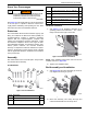
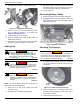
NOTE: See Figure 2-5. The actuator bracket (C) must
be positioned on the right hand side of the frame, with the
mounting hole towards the actuator to complete this pro-
cedure.
Figure 2-5. Actuator Bracket
3. Secure rear of actuator bracket to frame and dump
arm with a 5/16 in - 18 x 3 in flange bolt and lock-
nut.
4. Secure front of actuator bracket with a 5/16 in - 18
x 2-1/2 in flange bolt.
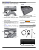
5. Secure the front/right and both left side locations of
bed frame to bed supports with three 5/16 in - 18 x
2-1/2 in flange bolts and locknuts.
6. Remove plastic protectors (if present) from end of
actuator.
7. See Figure 2-6. Secure end of actuator (D) to
actuator bracket with a 1/2 in - 13 x 1-1/2 in flange
bolt and locknut.
Figure 2-6. Actuator Assembly
Tailgate Installation
1. See Figure 2-7. Install tailgate onto front of bed
assembly.
Figure 2-7. Tailgate Installation
NOTE: Verify guide pins are fully into the bed and tabs at
both sides are locked into side walls.
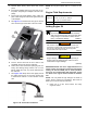
Installing Hour Meter
The hour meter is a reminder system that displays alerts
at regular intervals for oil changes, and displays accumu-
lated running times for long-term servicing needs.
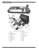
Figure 2-8. Parts Supplied For Hour Meter
006168
C
006169
D
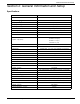
Parts Supplied For Hour Meter
Item # Description Qty
1 Hour meter / 66 in (1.7 m) wire 1
2 Panel plug 1
3 Cable ties 3
006170
(000102)
WARNING
Accidental Start-up. Disconnect spark plug wire when
working on unit. Failure to do so could result in death
or serious injury.
008081
1
2
3