Owner’s Manual Liquid-cooled, Prepackaged Standby Generators Model Number 005030-0 (15kW) 005028-0 (20kW) 005031-0 (25kW) This manual should remain with the unit.
INTRODUCTION Thank you for purchasing this model of the QuietSource™ standby generator series. Every effort was expended to make sure that the information and instructions in this manual are both accurate and current at the time the manual was written. However, the manufacturer reserves the right to change, alter or otherwise improve this product(s) at any time without prior notice.
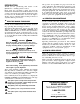
Table of Contents Liquid-cooled 15, 20 and 25 kW Generators INTRODUCTION ................................................IFC Section 3 — OPERATION ................................15 Read this Manual Thoroughly......................................IFC 3.1 Control Console Components..............................15 Operation and Maintenance ........................................IFC 3.2 Manual Transfer and Startup ..............................15 How to Obtain Service ................................
Important Safety Instructions Liquid-cooled 15, 20 and 25 kW Generators ! SAVE THESE INSTRUCTIONS – The manufacturer suggests that these rules for safe operation be copied and posted in potential hazard areas. Safety should be stressed to all operators, potential operators, and service and repair technicians for this equipment. ! SAVE THESE INSTRUCTIONS – This manual contains important instructions that should be followed during installation and maintenance of the generator and batteries.
Important Safety Instructions Liquid-cooled 15, 20 and 25 kW Generators ELECTRICAL HAZARDS FIRE HAZARDS • All generators covered by this manual produce dangerous electrical voltages and can cause fatal electrical shock. Utility power delivers extremely high and dangerous voltages to the transfer switch as well as the standby generator. Avoid contact with bare wires, terminals, connections, etc., on the generator as well as the transfer switch, if applicable.
Section 1 - General Information Liquid-cooled 15, 20 and 25 kW Generators 1.1 GENERATOR This equipment is a liquid-cooled, engine-driven generator set. The generator is designed to supply electrical power that operates critical electrical loads during utility power failure. The unit has been factory-installed in a weather resistant, all metal enclosure and is intended for outdoor installation only.
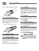
Section 1 - General Information Liquid-cooled 15, 20 and 25 kW Generators Figure 1.1 - Generator AC Connection System Figure 1.3 - Engine Protective Devices (BLACK) (WHITE) 0 NEUTRAL (BLACK) 1.6 MAIN CIRCUIT BREAKER The generator’s main circuit breaker is included with the unit as shipped from the factory. The breaker for each unit is described in Figure 1.2. 1.7 GENERATOR FUEL SYSTEM This unit has been factory tested and adjusted using a natural gas fuel system.
Section 1 — General Information Liquid-cooled 15, 20 and 25 kW Generators Figure 1.5- High Coolant Temperature Switch 1.8.6 LOW BATTERY The engine control board continually monitors the battery voltage and turns on the low battery LED if the battery voltage falls below 12 VDC for one minute. Low battery voltage is a non-latching alarm, which will automatically clear if the battery voltage rises above 12 VDC.
Section 1 — General Information Liquid-cooled 15, 20 and 25 kW Generators 1.11 SPECIFICATIONS 1.12 FUEL CONSUMPTION 1.11.1 ENGINE Make ......................................................................................Ford Displacement ............................................153 inches3 (2.5 liters) Cylinder Arrangement......................................................4, in-line Valve Arrangement................................................Overhead Cam Firing Order........................
Section 1 — General Information Liquid-cooled 15, 20 and 25 kW Generators 2. Remove the carburetor fuel hose from the outlet port (Port 1) of the demand regulator (Figure 1.8). 3. Remove the brass hose fitting from the outlet port (Port 1) of the demand regulator. 4. Remove pipe plug from Port 2. 5. Install brass hose fitting into Port 2. 6. Install pipe plug into Port 1. 7. Connect carburetor gas hose to brass fitting. 8. Tighten all clamps and plugs. 9.
Section 2 — Installation Liquid-cooled 15, 20 and 25 kW Generators 2.1 STANDBY GENERATOR INSTALLATION DANGER Connecting this generator to an electrical system normally supplied by an electric utility shall be by means of a transfer switch, so as to isolate the electric system from the utility distribution system when the generator is operating.
Section 2 — Installation Liquid-cooled 15, 20 and 25 kW Generators 2.4 BASIC STANDBY ELECTRIC SYSTEM Figure 2.1 shows a schematic diagram of a basic standby electric system. Both the UTILITY power supply and the STANDBY GENERATOR output are connected to an approved transfer switch. The transfer switch is required by electrical code and serves the following functions: • Permits the LOAD circuits to be connected to only one power supply at a time.
Section 2 — Installation Liquid-cooled 15, 20 and 25 kW Generators 2.8 GENERATOR AC NEUTRAL CONNECTIONS The manufacturer uses an UNGROUNDED AC neutral. Grounding is recommended only at the main service entrance. If the neutral wire is grounded and one of the phase loads becomes grounded, the excessive current opens the load circuit breaker or collapses the generator field. The actual result depends on the electrical characteristics of the particular installed generator. 2.
Section 2 — Installation Liquid-cooled 15, 20 and 25 kW Generators 2.10 ENGINEERED TRANSFER SWITCH (2-WIRE START GTS MODE) When required, the pre-packaged standby generator can be installed with an engineered W Type transfer switch which controls utility voltage sensing, weekly exercising and load transferring. When Position 2 of the eight-position DIP switch, which is located on the generator circuit board (See Figure 3.
Section 2 — Installation Liquid-cooled 15, 20 and 25 kW Generators Transfer Switch terminals N1 and N2 (also called Utility 1 and Utility 2) are the input utility AC power connections to the Transfer Switch. Transfer Switch terminals T1 and T2 (also called Load 1 and Load 2) are the transfer switch AC output power terminals that go to the load circuit distribution panel. Transfer Switch terminals E1 and E2 are the AC power terminals that come from the generator's main alternator.
Section 2 — Installation Liquid-cooled 15, 20 and 25 kW Generators The recommended battery is Group 26, 12VDC, 550 CCA/75 AH minimum. All batteries must be at 100 percent state-of-charge before they are installed on the generator. When using maintenance-free batteries, it is not necessary to check the specific gravity or electrolyte level. Have these procedures performed at the intervals specified in Section 4, “Maintenance.” A negative ground system is used.
Section 3 - Operation Liquid-cooled 15, 20 and 25 kW Generators 3.1 See Section 1.7 for further explanation of engine protection functions. CONTROL CONSOLE COMPONENTS The components of a home standby generator control console (Figure 3.1) are as follows: Figure 3.1 - Generator Control Console CAUTION OVER CRANK OVER SPEED LOW COOL. LEVEL HI COOL. TEMP. LOW OIL PRESS. RISK OF ELECTRICAL SHOCK. DO NOT REMOVE COVER. NO USER SERVICEABLE PARTS INSIDE. REFER SERVICING TO QUALIFIED SERVICE PERSONNEL.
Section 3 - Operation Liquid-cooled 15, 20 and 25 kW Generators Condition System Ready (Green) Low Bat (Red) Low Oil (Red) High Temp (Red) Over Speed (Red) Over Crank (Red) Generator Switch is in the OFF Mode. OFF X OFF OFF OFF OFF System Ready for Automatic Start ON X OFF OFF OFF OFF Generator Switch is in the MANUAL Mode OFF X OFF OFF OFF OFF Weekly Exerciser is not set X Battery Voltage <12.
Section 3 - Operation Liquid-cooled 15, 20 and 25 kW Generators 6. Reduce load to 3/4, 1/2, 1/4 and no load. Decrease the stability pot if there is instability at any load point. 7. Adjust differential pot to make the recovery to load changes even faster and minimize load change undershoot and overshoot. If it is set too high, it may introduce oscillations at some load. It can be set to zero (full CCW) if a small amount causes oscillations at some load. 8. Leave DIP switch 8 in TEST mode. 3.
Section 3 - Operation Liquid-cooled 15, 20 and 25 kW Generators 3.7 CONTROL BOARD DIP SWITCH SETTINGS Located on the control board is an eight position DIP switch (see Figure 3.2). The eight different switches, are used to configure the control board for the specific engine and governor being used and are pre-set at the factory. ! 3.8 VOLTAGE REGULATOR ADJUSTMENT Four adjustment potentiometers are provided on the voltage regulator installed in the control panel (Figure 3.4).
Section 4 — Maintenance Liquid-cooled 15, 20 and 25 kW Generators 7. Turn the voltage regulator’s VOLTAGE ADJUST pot to obtain a line-to-line voltage of: A. 240 VAC if the generator has been configured for 60 Hertz operation. B. 200 VAC if the generator has been configured for 50 Hertz operation. 8. If the RED REGULATOR LED is flashing, adjust the STABILITY pot in either direction until the flashing stops. 9. Apply an electrical load and check the engine speed recovery. A.
Section 4 — Maintenance Liquid-cooled 15, 20 and 25 kW Generators 3. Install a new lower intake manifold gasket. 4. Position the lower intake manifold to the cylinder head. 5. Install retaining bolts/studs finger tight. 6. Tighten all bolts/studs to specifications in the tightening sequence shown: • First pass = 7=10 N-m (5-7 lb-ft). • Final pass = 26-38 N-m (19-28 lb-ft). 4.4 CYLINDER HEAD PROCEDURE 1. Position head gasket on the block (Figure 4.2). 2. Position cylinder head to cylinder block. 3.
Section 4 — Maintenance Liquid-cooled 15, 20 and 25 kW Generators 4.7.2 BATTERY FLUID Check battery electrolyte fluid based on the Maintenance Schedule. Fluid should cover separators in all battery cells. If fluid level is low, add distilled water to cover tops of separators. DO NOT USE TAP WATER IN BATTERY. 4.7.3 ENGINE COOLANT Check coolant level in coolant recovery bottle. See Specifications. • Add recommended coolant mixture as necessary.
Section 4 — Maintenance Liquid-cooled 15, 20 and 25 kW Generators 5. Apply light coating of new engine oil to seal of new oil filter. Install FILTER and tighten by hand only. DO NOT OVER TIGHTEN. 6. Remove OIL FILL CAP. Add recommended oil (see SPECIFICATIONS). DO NOT FILL ABOVE THE DIPSTICK “FULL” MARK. Crankcase oil capacity is 4.0 U.S. quarts (3.8 liters). After refilling the crankcase with oil, always ! check oil level on dipstick. NEVER OPERATE ENGINE WITH OIL BELOW THE DIPSTICK “ADD” MARK. 7.
Section 4 — Maintenance Liquid-cooled 15, 20 and 25 kW Generators 4.9.3 BATTERY MAINTENANCE The battery should be inspected per Section 4.7, Scheduled Maintenance. The following procedure should be followed for inspection: 1. Inspect the battery posts and cables for tightness and corrosion. Tighten and clean as necessary. 2. Check the battery fluid level of unsealed batteries and, if necessary, fill with DISTILLED WATER ONLY. Do not use tap water in batteries. 3.
Section 4 — Maintenance Liquid-cooled 15, 20 and 25 kW Generators 4.10 SCHEDULED MAINTENANCE The following is a recommended maintenance schedule for small standby and residential generator sets. The established intervals in the schedule are the maximum recommended when the unit is used in an average service application. They will need to be decreased (performed more frequently) if the unit is used in a severe application.
Section 4 — Maintenance Liquid-cooled 15, 20 and 25 kW Generators Maintenance Tasks Level 1 Recommended to be done monthly Level 2 Task Comp. (DateInitials) Required to be done 3 months/ Break-in Level 3 Task Comp. (DateInitials) Required to be done Semiannually Level 4 Task Comp. (DateInitials) Required to be done Annually Task Comp. (DateInitials) 1. Disable the unit from operating per the first page warning. 2. Check the engine oil level. Adjust as necessary. 3. Check the engine coolant level.
Section 4 — Maintenance Liquid-cooled 15, 20 and 25 kW Generators Maintenance Tasks 13. Initiate an automatic start and transfer of the unit to site load and exercise it for at least 1 hour looking for leaks, loose connections or components, and abnormal operating conditions. Correct as necessary. 14. Start and exercise the unit at full rated load (use a load bank if the site load is not enough) for at least 2 hours looking for leaks, loose connections or components, and abnormal operating conditions.
Section 5 — Troubleshooting Liquid-cooled 15, 20 and 25 kW Generators TROUBLESHOOTING POINTS PROBLEM CAUSE CORRECTION Engine won’t crank. 1. 15 amp fuse blown. 2. Loose or corroded or defective battery cables. 3. Defective starter contactor. 4. Defective starter motor. 5. Dead or Defective Battery. 6. 5 amp fuse blown. 1. Replace fuse. 2. Tighten, clean or replace battery cables as necessary. 3. Replace contactor. 4. Replace starter motor. 5. Remove, change or replace battery. 6. Replace fuse.
Section 6 — Notes Liquid-cooled 15, 20 and 25 kW Generators 28
Section 6 — Notes Liquid-cooled 15, 20 and 25 kW Generators 29
Section 7 - Electrical Data Liquid-cooled 15, 20 and 25 kW Generators Wiring Diagram — 2.5L Engine (15kW & 20kW units) —Drawing No.
Section 7 - Electrical Data Liquid-cooled 15, 20 and 25 kW Generators Wiring Diagram — 2.5L Engine (15kW & 20kW units) —Drawing No.
Section 7 - Electrical Data Liquid-cooled 15, 20 and 25 kW Generators Electrical Schematic — 2.5L Engine (15kW & 20kW units) —Drawing No.
Section 7 - Electrical Data Liquid-cooled 15, 20 and 25 kW Generators Electrical Schematic — 2.5L Engine (15kW & 20kW units) —Drawing No.
Section 7 - Electrical Data Liquid-cooled 15, 20 and 25 kW Generators Wiring Diagram — 2.5L Engine (25kW unit) —Drawing No.
Section 7 - Electrical Data Liquid-cooled 15, 20 and 25 kW Generators Wiring Diagram — 2.5L Engine (25kW unit) —Drawing No.
Section 7 - Electrical Data Liquid-cooled 15, 20 and 25 kW Generators Electrical Schematic — 2.5L (25kW unit) — Drawing No.
Section 7 - Electrical Data Liquid-cooled 15, 20 and 25 kW Generators Electrical Schematic — 2.5L (25kW unit) — Drawing No.
Section 8 - Exploded Views and Parts Lists Liquid-cooled 15, 20 and 25 kW Generators Mounting Base — Drawing No.
Section 8 - Exploded Views and Parts Lists Liquid-cooled 15, 20 and 25 kW Generators Mounting Base — Drawing No. 0F0104-B ITEM 1 2 3 4 5 6 7 8 9 10 11 12 13 14 15 16 17 18 19 20 21 22 23 24 25 26 27 28 29 30 31 32 33 34 35 36 37 PART NO. 0F1705 0E8834 0E9911 049813 022097 026850 055414 022473 047411 052860 052251 052257 052252 052259 052891 0536210261 074906 077483 0F0796 025507 060619 046526 022131 021991 038805G 050331 050331A 038804J 045771 022129 027482 075763 0E9748A 0F0795 0C2454 065852 045764 QTY.
40 30 32 31 LATCH DETAIL 3 31 32 34 18 17 39 45 38 40 4 4 5 25 9 33 2 STATES FOAM IS ON FAR SIDE STATES FOAM IS ON NEAR SIDE 29 "B" 36 33 25 4 32 4 39 17 10 11 46 SEE LATCH DETAIL 18 17 47 18 48 TYPICAL OF ROOF PANEL THAT REQUIRE INSULATION. SECURE AS SHOWN.
Section 8 - Exploded Views and Parts Lists Liquid-cooled 15, 20 and 25 kW Generators Enclosure — Drawing No. 0F1645-H ITEM 1 2 3 4 5 6 7 8 9 10 11 12 13 14 15 17 18 19 20 21 22 23 24 25 26 27 28 29 30 31 32 33 34 35 36 37 38 39 40 41 42 43 44 45 46 47 48 PART NO.
Section 8 - Exploded Views and Parts Lists Liquid-cooled 15, 20 and 25 kW Generators Control Panel (15kW and 20kW) — Drawing No.
Section 8 - Exploded Views and Parts Lists Liquid-cooled 15, 20 and 25 kW Generators Control Panel (15kW and 20kW) — Drawing No. 0F2267-D ITEM 1 2 3 4 5 6 7 8 9 10 11 12 13 14 15 16 17 18 19 20 21 22 23 24 25 26 27 28 29 30 31 32 33 34 35 36 37 38 39 40 41 42 43 44 45 PART NO.
Section 8 - Exploded Views and Parts Lists Liquid-cooled 15, 20 and 25 kW Generators Control Panel (25kW) — Drawing No.
Section 8 - Exploded Views and Parts Lists Liquid-cooled 15, 20 and 25 kW Generators Control Panel (25kW) — Drawing No. 0E7615-C ITEM 1 2 3 4 5 6 7 8 9 10 11 12 13 14 15 16 17 18 19 20 21 22 23 24 25 26 27 28 29 30 31 32 33 34 35 37 38 39 40 41 42 43 44 PART NO.
30 46 41 20 30 19 20 29 27 60 39 20 59 28 38 19 14 39 16 52 40 25 38 4 10 13 2 0 17 15 22 31 5 19 45 19 3 47 FOR HARNESS GROUND 20 HSG. 20 3 68 34 17 22 15 1 50 35 49 39 16 65 33 15 8 66 67 18 20 12 61 37 "A" 57 16 11 18 62 17 58 38 23 TO RADIATOR CAP 39 24 STEPPER MOTOR UNITS ONLY Section 8 - Exploded Views and Parts Lists Liquid-cooled 15, 20 and 25 kW Generators Engine — Drawing No.
Section 8 - Exploded Views and Parts Lists Liquid-cooled 15, 20 and 25 kW Generators Engine — Drawing No. 0E9918-F ITEM PART NO. QTY.
48 12 TO VALVE 1 COVER 17 20 28 TO ENGINE 10 32 31 8 33 18 42 30 6 26 7 35 22 21 38 34 16 24 25 13 9 41 PORT "OUT 2" 3 11 4 15 29 CARBURETOR ASSY. 0E1028A (I/N 19) L.P. VAPOR CONVERSION 40 5 27 1 4 6 3 40 11 2 PORT "OUT 1" 6 7 Section 8 - Exploded Views and Parts Lists Liquid-cooled 15, 20 and 25 kW Generators Fuel System — Drawing No.
Section 8 - Exploded Views and Parts Lists Liquid-cooled 15, 20 and 25 kW Generators Fuel System — Drawing No. 0E9980-D ITEM 1 2 3 4 5 6 7 8* 9 10 11 12 13 14 15 16 * 17 18 19 20 21 * 22 * 23 24 25 26 27 28 29 30* 31* 32* 33* 34* 35* 36* 37* 38* 39* 40 41 42 PART NO.
Section 8 - Exploded Views and Parts Lists 12 8 7 5 18 50 LOCKTIGHT 15 7 17 1 4 16 31 30 LEADS 2 6 9 21 13* LOCKTIGHT 3 10 11 20 19 14 Liquid-cooled 15, 20 and 25 kW Generators Alternator — Drawing No.
Section 8 - Exploded Views and Parts Lists Liquid-cooled 15, 20 and 25 kW Generators Alternator — Drawing No. 0E8660-C ITEM PART NO. QTY.
Section 8 - Exploded Views and Parts Lists Liquid-cooled 15, 20 and 25 kW Generators Muffler — Drawing No. 0F2930-C 1 5 4 24 6 7 11 3 17 19 20 13 15 20 12 11 20 5 7 4 6 18 6 15 14 16 9 8 10 2 21 22 23 ITEM 1 2 3 4 5 6 7 8 9 10 11 12 52 PART NO. 0F2912 0F2869 0F2823 036434 036449 022129 022259 0E0170A 044149 0E8816 0F2925 0F2926 QTY. 1 1 1 2 2 6 4 1 1 1 2 1 DESCRIPTION PIPE MUFFLER OUT PIPE EXHAUST 2.5L FORD MUFFLER 2.5L FORD BOLT U 5/16-18 X 2.
Section 8 - Exploded Views and Parts Lists Liquid-cooled 15, 20 and 25 kW Generators Stepper Motor — Drawing No. 0E9979-C 5 4 3 ITEM (13) NEOPRENE COATING 2 1 14 6 7 10 WIRE HARNESS 15 12 9 "A" 10 7 CARBURETOR ARM (REF.) 6 SECURE WIRE HARNESS WITH TIE WRAP AS SHOWN. 7 16 17 TO "A" INTAKE MANIFOLD (REF.) 11 ITEM 1 2 3 4 5 6 7 8 9 10 11 12 13 14 15 16 17 18 PART NO.
Section 8 - Exploded Views and Parts Lists Liquid-cooled 15, 20 and 25 kW Generators Radiator — Drawing No. 0E9965-F 1 19 18 12 5 11 2 14 26 TO THERMOSTAT ADAPTER 5 9 18 7 8 10 5 25 5 TO BASE OF WATER INLET TUBE (ON BLOCK) 9 7 24 15 3 16 9 1 2 3 4 5 6 7 8 9 10 11 12 14 54 PART NO. QTY. 0E9769 0F0779 0E9769A REF REF REF 0E9837 0F0123 0F0118 099502 0C2454 052250 022097 022473 022127 046627 060035 0F0127 1 1 1 4 REF. 2 8 12 8 1 4 1 DESCRIPTION SUPPORT RADIATOR 2.
Section 9 — Installation Diagram Liquid-cooled 15, 20 and 25 kW Generators Installation Diagram — Drawing No.
Section 10 – Warranty Liquid-cooled 15, 20 and 25 kW Generators CALIFORNIA EMISSION CONTROL WARRANTY STATEMENT YOUR WARRANTY RIGHTS AND OBLIGATIONS The California Air Resources Board (CARB) and Generac Power Systems, Inc. (Generac) are pleased to explain the Emission Control System Warranty on your new engine.* In California, new utility, and lawn and garden equipment engines must be designed, built and equipped to meet the state’s stringent anti-smog standards.
Section 10 – Warranty Liquid-cooled 15, 20 and 25 kW Generators EMISSION CONTROL SYSTEM WARRANTY Emission Control System Warranty (ECS Warranty) for 1995 and later model year engines: (a) Applicability: This warranty shall apply to 1995 and later model year engines. The ECS Warranty Period shall begin on the date the new engine or equipment is purchased by/delivered to its original, end-use purchaser/owner and shall continue for 24 consecutive months thereafter.
Section 10 – Warranty Liquid-cooled 15, 20 and 25 kW Generators GENERAC POWER SYSTEMS "TWO YEAR" LIMITED WARRANTY FOR QUIETSOURCE™ "PREPACKAGED EMERGENCY AUTOMATIC STANDBY GENERATORS" For a period of two years from the date of original sale, Generac Power Systems, Inc. (Generac) warrants that its Quietsource generator will be free from defects in material and workmanship for the items and period set forth below.