
Installation Guide

Fuel Conversion / Gas Connections
Installation Guidelines For Australian 50 Hz Air-Cooled Generators 23
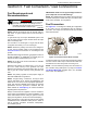
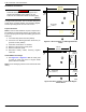
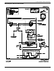
2. See Figure 5-5. Mount the DIN rail (A) to the drilled
holes in the engine divider panel with two M4-0.7 X
10 (8-32 x 0.5 in) fasteners and nuts.
Figure 5-5. Mount DIN Rails and Relays
3. Both control relays (B) mount to the DIN rail
through the eyelets provided on the relays.
4. Clip the timer relay (C) onto the DIN rail between
the two control relays.
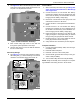
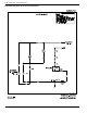
Timer Relay Settings
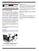
5.
See
Figure 5-6
. The timer relay includes an adjust-
able timing dial (1), a fine time dial (2) to be set full
clockwise, and a function dial (3) to be set at “D.”
Figure 5-6. Timer Relay Settings
Connect Wires
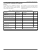
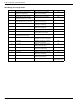
1. Wire control relays and timer relay per Wiring Dia-
gram—AU Fuel Field Install Kit and Wire Gauge
and Length Chart.
2. Connect kit wire Q to unit harness wire #86 by
inserting and crimping the 6 mm stripped end of kit
wire Q into the factory connected bullet connector
hanging near the battery charger plug.
3. Disconnect unit harness #14 wire (red) at the fuel
solenoid and connect it to kit wire D.
4. Connect kit wire C to the exposed fuel solenoid ter-
minal.
5. Connect kit wire P to unit harness wire #56 by
inserting and crimping the 6 mm stripped end of
the kit wire P into the factory connected blade con-
nector hanging near the battery charger plug.
6. Install gas pressure sensor(s) in line with the fuel
supply. Configure to the proper setting for desired
fuel type using the gas pressure switch manual.
7. Route kit wires G, H, and S from inside the unit out
to the gas pressure sensor switch(es).
8. Verify all other wire connections per wire diagram.
Complete Installation
1. Connect the positive battery cable, then the nega-
tive battery cable.
2. Install the intake side panel.
3. Install the 7.5A fuse in the control panel.
4. Set the MLCB (generator disconnect) on the gen-
erator to ON (CLOSED).
5. Turn the main utility disconnect ON (CLOSED).
NOTE: Verify functionality of the fuel kit prior to complet-
ing installation and leaving the unit in AUTO mode.
005670
B
A
B
C
006094
1 sec-
10 day
1
10
ON
OFF
1
1
10
1
10
10
m
S
h
d
B
A
C
D
E
F
G
H
I
J
3
1
2