
Installation Guide


Electrical Connections
Installation Guidelines For Australian 50 Hz Air-Cooled Generators 33
.
Main AC Wiring
NOTE: Main AC wiring must be in accordance with local
jurisdiction and codes.
NOTE: The generator lugs are rated at 75 °C (167 °F),
copper or aluminum.
1. Strip the insulation off the wire ends. Do not
remove excessive insulation.
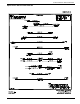
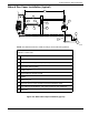
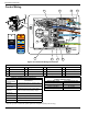
2. See Figure 6-1. Loosen the lugs at neutral (E2),
ground (G), and power wire (mains) terminal (E1).
3. Connect the ground wire to the ground lug and
torque to the required specification. See Table 6-4.
4. Insert the power wire and neutral wire (E1 and E2)
into their corresponding lugs. Torque to the proper
specification.
5. Verify the factory-installed ground array and neutral
connections are properly tightened to 2.82 Nm (25
in-lbs).
NOTE: Torque all wiring lugs, bus bars, and connection
points to the proper torque specifications.
Conductors of AC and DC circuits, rated 1,000 volts
nominal or less, shall be permitted to occupy the same
equipment, cable, or conduit. All conductors shall have
an insulation rating equal to at least the maximum circuit
voltage applied to any conductor within the equipment,
cable, or conduit. See NEC 300.3(C)(1).
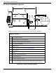
Common Alarm Relay (Option)
Alarms relating to generator and engine performance
appear on the controller. The controller is equipped with a
common alarm relay that provides contacts for an
optional customer-supplied external alarm indicator.
The common alarm relay is normally open until an alarm
occurs, triggering the relay to close the contacts.
Terminals for the common alarm relay are provided in the
wiring harness near the controller plug (Wires 209 and
210).
Contact rating is for resistive load only:
Battery Requirements
12 volts, Group 26R-540CCA minimum, or Group
35AGM-650CCA minimum.
NOTE: Do not use external battery chargers.
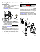
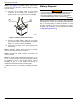
Battery Installation
• (Group 26R batteries only): Fill the battery with
the proper electrolyte fluid if necessary.
• Fully charge the battery before installing it.
Complete the following steps before installing and con-
necting the battery:
1. Verify the generator is OFF.
2. Turn OFF utility power supply to the transfer
switch.
3. Remove the 7.5A fuse from the generator control
panel.
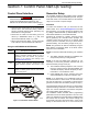
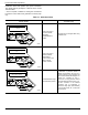
Table 6-4. Ground and Neutral Connections
(Copper or Aluminum Conductors)
Refer to national and/or local codes to verify correct wire sizes.
No. Description
Recommended
Wire Size
Torque Spec
1
Power wire
terminal (E1)
2/0 to 8 AWG 13.56 Nm (120 in-lbs)
2
Neutral lug
terminal (E2)
2/0 to 14 AWG 13.56 Nm (120 in-lbs)
3
Ground lug
terminal (G)
2/0 to 14 AWG 13.56 Nm (120 in-lbs)
4
Alternator
Winding
Junction Bar
8 AWG
10 AWG
2.82 Nm (25 in-lbs)
2.26 Nm (20 in-lbs)
Contact rating 200 mA at 12 VDC
(000137a)
WARNING
Explosion. Batteries emit explosive gases while charging.
Keep fire and spark away. Wear protective gear when
working with batteries. Failure to do so could result in
death or serious injury.
(000138a)
WARNING
(000133)
WARNING
Explosion. Batteries emit explosive gases.
Always connect positive battery cable first to
avoid spark. Failure to do so could result in
death or serious injury.