
Installation Guide
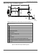
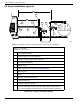


Electrical Connections
32 Installation Guidelines For Australian 50 Hz Air-Cooled Generators
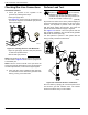
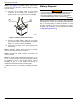
Control Wiring
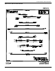
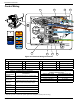
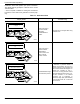
Figure 6-1. Electrical Wiring Connections
* Must be connected to keep battery charged whether unit is running or not.
** Required if generator is paired with optional Digital Power Management (DPM) smart technology.
Table 6-1. Electrical Wiring Connection Points
ID Description ID Description ID Description ID Description
A Control wire terminal block C2 Wire tie for control wires E2 Neutral
H
Alternator winding junction
B Sense wire terminal block D No service connections F Ground stud
—
—
C1 Wire tie for sense wires E1 Power lug E1 G Ground lug
—
—
005967
1
1
2
2
3
3
0
194
23
2
2
4
4
N2
T2
3
3
T1
1
1
N1
A
B
C1
C2
E1
E2
H
D
F
G
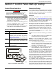
Table 6-2. Customer Wiring Connections
Terminal
Numbering Decal
Wire Numbers
ORANGE /
YELLOW TAG
N1—Fused 220-230-240 VAC, 6A - Sensing for utility
power dropout and pickup
LIGHT BLUE /
YELLOW TAG
N2—Neutral for N1
ORANGE / DARK
BLUE TAG*
T1—Fused 220-230-240 VAC, 6A for battery charger.
Must be on a backed-up circuit to power the generator
controller at all times and keep the battery charged.
LIGHT BLUE /
DARK BLUE TAG *
T2—Neutral for T1 battery charger
WHITE **
0—DC (-) Common ground wire
BLACK
194—DC (+) 12 VDC for transfer control
BLUE
23—Transfer control signal wire
Table 6-3. Control Wire Recommended Length and Size
(Copper conductors only)
Maximum Wire Length Recommended Wire Size
0.3–35 m (1–115 ft) No. 18 AWG
35–56 m (115–185 ft) No. 16 AWG
56–89 m (185–295 ft) No. 14 AWG
89–140 m (295–460 ft) No. 12 AWG