
Installation Guide

Fuel Conversion / Gas Connections
22 Installation Guidelines For Australian 50 Hz Air-Cooled Generators
Installation Instructions
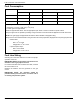
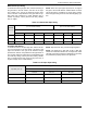
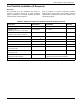
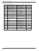
Throughout this procedure, refer to the Wire Gauge and
Length Chart, the wiring diagram, the schematic diagram,
and the splice diagram at the end of this section.
Prepare Generator
NOTE: This fuel field install kit requires components to
be installed in the gas supply piping to the generator. Ver-
ify gas is properly shut off prior to installing gas pressure
switch(es).
1. Turn main utility disconnect OFF (OPEN).
2. Lift lid and turn MLCB (generator disconnect) on
generator to OFF (OPEN).
3. Press OFF mode button on controller.
4. Remove 7.5A fuse from control panel.
5. Remove intake side panel.
6. Disconnect battery cables, removing negative
cable first.
Install DIN Rail and Relays
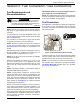
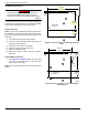
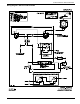
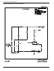
1. See Figure 5-3 or Figure 5-4. Drill two 5 mm (0.20
in) holes in upper right corner of engine divider
panel under the controller.
NOTE: Avoid damaging harness wires and decals while
drilling.
Figure 5-3. Hole Locations—8 kVA Engine Divider
Panel
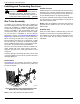
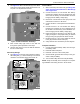
Figure 5-4. Hole Locations—10 & 13 kVA Engine
Divider Panel
Automatic start-up. Disconnect utility power and
render unit inoperable before working on unit.
Failure to do so will result in death or serious injury.
(000191)
DANGER
005669
2X Ø 5 mm
(0.20 in.)
170 mm
(6.69 in)
100 mm
(3.94 in)
36 mm
(1.42 in)
006808
2X Ø 5 mm
(0.20 in.)
125 mm
(4.92 in)
36 mm
(1.42 in)
100 mm
(3.94 in)