
Product Manual
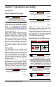
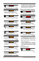
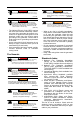

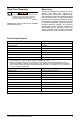


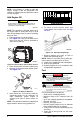
Table Of Contents
- iQ3500 Portable Generator Owner’s Manual
- Generador portátil iQ3500 Manual del usuario
- Índice de contenidos
- Sección 1 Introducción y seguridad
- Sección 2 Información general y configuración
- Conozca su generador
- Emisiones
- Enchufes de conexión
- Contador de pantalla digital
- Interruptor de apagado/ encendido/cebado
- Salidas USB
- Interruptor de ahorro
- Luces de estado del generador
- Protectores del circuito
- Retiro del contenido de la caja
- Conexión del cable de la batería (si se incluye)
- Añadir aceite de motor
- Combustible
- Sección 3 Funcionamiento
- Preguntas sobre uso y funcionamiento
- Antes de arrancar el motor
- Preparación del generador para su uso
- Conexión a tierra del generador cuando se utiliza
- Conozca los límites del generador
- Transporte/inclinación de la unidad
- Arranque de motores con el tirador de arranque
- Arranque de motores con arranque eléctrico
- Volver a arrancar motores calientes
- Sistema de cierre por nivel bajo de aceite
- Funcionamiento en paralelo
- Sección 4 Mantenimiento y solución de problemas
- Pieza Nº 10000033207
- Générateur portatif iQ3500 Manuel du propriétaire
- Table des matières
- Section 1 Introduction et règles de sécurité
- Section 2 Informations générales et installation
- Connaître son générateur
- Émissions
- Fiches de raccordement
- Compteur à affichage numérique
- Commutateur de mise à l’arrêt/ mise en marche/commande d’étrangleur
- Ports USB
- Commutateur de fonctionnement au ralenti
- Témoins d'état du générateur
- Dispositifs de protection de circuits
- Retrait des pièces du colis
- Raccordement des câbles de batterie (le cas échéant)
- Ajout d’huile moteur
- Carburant
- Section 3 Fonctionnement
- Questions relatives au fonctionnement
- Avant de démarrer le moteur
- Préparation du générateur à l’utilisation
- Mise à la terre du générateur une fois en fonctionnement
- Connaître les limites de son générateur
- Transport/Inclinaison de l’appareil
- Démarrage des moteurs à démarrage manuel
- Démarrage des moteurs à démarrage électrique
- Démarrage des moteurs à chaud
- Système d’arrêt en cas de faible niveau d’huile
- Fonctionnement en parallèle
- Section 4 Maintenance et dépannage
- Réf. 10000033207

Owner’s Manual for Portable Generator 7
Generator Status Lights
See Figure 2-7.
• Overload LED (red): Indicates system
overload (2). During motor starting it is nor-
mal for the overload LED to illuminate for a
few seconds. If LED stays illuminated and
the ready LED turns off, the engine will con-
tinue to run without output power. Remove
all applied loads and determine if attached
devices exceed recommended output
power. Check for faulty or shorted connec-
tions. To restore electrical output, turn dial
OFF to reset. Start engine. If condition was
corrected, the orange LED will not illumi-
nate and electrical output will be restored.
Loads can be applied once the green LED
illuminates. If the orange LED returns, con-
tact an IASD.
• Low Oil Level LED (yellow): Illuminates
when oil level is below safe operating level.
Engine shuts down (1).
• Power LED (green): Indicates output from
generator (3) (unless there is a low oil or
overload condition).
Figure 2-7. Status Indicators
Circuit Protectors
The AC receptacles are protected by an AC
circuit protector. If the generator is overloaded
or an external short circuit occurs, the circuit
protector will trip. If this occurs, disconnect all
electrical loads to determine the cause of the
problem before using the generator again.
Reduce the load if the circuit protector is
tripped.
NOTE: Continuous tripping of the circuit pro-
tector may cause damage to generator or
equipment.
Push the button of the protector to reset the
circuit protector.
Remove Contents from Carton
1. Open carton completely by cutting each
corner from top to bottom.
2. Remove and verify carton contents prior to
assembly. Carton contents should contain
the following:
Accessories
3. Call Generac Customer Service at 1-888-
GENERAC (1-888-436-3722) with the unit
model and serial number for any missing
carton contents.
4. Record model, serial number, and date of
purchase on front cover of this manual.
Battery Cable Connection (if
equipped)
The unit has been shipped with the battery
cables disconnected.
See Figure 2-7.
1. Use a Phillips screwdriver to remove the
screw from the battery door.
2. Remove battery strap (1) from battery (2).
Figure 2-8. Battery Connection
3. First, connect the red cables to the positive
(+) battery terminal with the bolt and nut
supplied.
4. Make sure connections are secure and
slide rubber boot over the positive (+) bat-
tery terminal and connection hardware.
5. Connect the black cables to the negative
(-) battery terminal with the bolt and nut
supplied. Slide rubber boot over the neg-
ative (-) battery terminal and connection
hardware.
6. Make sure all connections are secure.
OVERLOAD OUT
PU
T
1
2
3
005483
Item Qty.
Main Unit 1
Owner’s Manual 1
Engine Oil 1
Oil Funnel 1
Tool Kit 1
Service Warranty 1
Emissions Warranty 1
(000167a)
CAUTION
Equipment damage. Do not make battery
connections in reverse. Doing so will result
in equipment damage.
OUTPUT
FAULT
007843
2
1