
Install Manual


Electrical Connections
Installation Manual for Generac PWRCell Inverter 19
Connecting CTs to the Inverter
•
See Figure 5-8. Connect CTs to the inverter using
a RJ-45 connector and Category 5 (Cat 5) Ethernet
cable.
• CT input jack (H) is a double-stacked RJ-45 jack.
Either the top or bottom jack may be used.
NOTE: Connect CT
s to the CT input jack in the middle of
the wiring compartment. Do not connect CTs to the
Ethernet jack. Do not connect the Internet to the CT input
jack. See Generac PWRcell Inverter Wiring
Compartment for jack locations.
:
010001
H
I
J
K
L
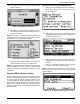
Figure 5-8. Accessory Ports
H CTs RJ-45 jack
I ATS (Automatic Transfer Switch) RJ-45 jack
J REbus Beacon USB-B
K Authorized Generac personnel only
L External safety shutdown switch terminals
• See Figure 5-9. Connect CT leads to RJ-45
Breakout Adapter (M), using the wire coding shown
in Table 5-8: CT Pinout.
010002
M
Figure 5-9. RJ-45 Breakout Adapter
NOTE: RJ-45 Breakout Adapter is included in the
Generac PWRcell Kit.
NOTE: If the RJ-45 Breakout Adapter is not available,
the CT leads can be wired to a Cat 5 cable.
Table 5-8. CT Pinout
Pin
Wire Color
(T-568A)
Wire Color
(T-568B)
Value
1 White/Green White/Orange CT3+
2 Green Orange CT3-
3 White/Orange White/Green CT2+
4 Blue Blue CT1+
5 White/Blue White/Blue CT1-
6 Orange Green CT2-
7 White/Brown White/Brown Not Used
8 Brown Brown Not Used
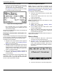
CT Calibration
•
Install CTs before powering ON the inverter.
• The inverter automatically detects and calibrates
CTs when turned ON.
• Once CTs are detected and calibrated, a utility pole
symbol will appear on the lower right corner of the
home screen power flow diagram.
• If manual CT calibration is required, set
CalOverride to 1. The CalOverride setpoint is
accessible through the Mod. Settings menu via the
inverter device page. See Table 5-9 for more
information.
– CT1 must be connected to Line 1.
– CT2 must be connected to Line 2.
– CT3 must be connected to line 3 (for three phase
applications).
– All CTs must be pointed such that positive cur-
rent defined by the arrow of the CT is pointed
towards the grid.
Table 5-9. CT Setpoints
Setpoint Behavior Default Units
C
• Overrides automatic CT detection.
• When set to 0, the inverter automatically detects the CTs number and
direction of CTs.
• A value of 1 assumes a specific orientation and direction of CTs.
0 N/A
CTTurnsRatio
• Turns ratio of the CTs installed.
• Default turns ratio of 1500 is compatible with included clamp type CT's
• If installation restriction requires larger accessory CT's, set point shall be
adjusted to 3000.
1500 Turns