
Installation Guide


Table Of Contents
- Installation Guidelines 60 Hz Air-Cooled Generators
- Table of Contents
- Section 1: Safety Rules & General Information
- Section 2: Unpacking and Inspection
- Section 3: Site Selection and Preparation
- Section 4: Generator Placement
- Section 5: Fuel Conversion / Gas Connections
- Section 6: Electrical Connections
- Section 7: Control Panel Startup / Testing
- Section 8: Troubleshooting
- Section 9: Quick Reference Guide
- Section 10: Accessories
- Section 11: Diagrams
Fuel Conversion / Gas Connections
Installation Guidelines for 60 Hz Air-Cooled Generators 23
Natural Gas Pipe Sizing
To determine correct NG pipe size, find the kW rating of
generator in the left column, and trace to the right. The
number to the right is maximum length (measured in ft /
m) allowed for the pipe sizes on top. Pipe sizes are mea-
sured by trade size diameter to include any fittings,
valves (must be full flow), elbows, tees, or angles.
NOTE: See Table B.3.2 in NFPA 54 or Table A.2.2 in the
ICC IFGC, Equivalent Lengths of Pipe Fittings and
Valves for the correct values to be added to overall fuel
piping length. Tables are based on schedule 40 black
pipe. If installing any other piping system, follow pipe siz-
ing charts for selected piping system.
LP Gas Pipe Sizing
To determine correct LP gas pipe size, find the kW rating
of generator in the left column, and trace to the right. The
number to the right is maximum length (measured in ft /
m) allowed for pipe sizes on top. Pipe sizes are mea-
sured by trade size diameter to include any fittings,
valves (must be full flow), elbows, tees, or angles. See
Table B.3.2 in NFPA 54 or Table A.2.2 in the ICC IFGC,
Equivalent Lengths of Pipe Fittings and Valves for the
correct values to be added to overall fuel piping length.
NOTE: Pipe sizes are from the outlet of the second
stage regulator to the fuel shutoff valve. Table is based
on schedule 40 black pipe. If installing any other piping
system, follow the pipe size charts for the selected piping
system.
NOTE: Recommended minimum LP tank size is 250 gal
(946 L). Contact LP provider to correctly size LP tank to
generator. Vertical tanks, which are measured in pounds
(or kilograms), are permitted if correctly sized for the gen-
erator. Do not connect generator to a 20 or 30 lbs LP
tank.
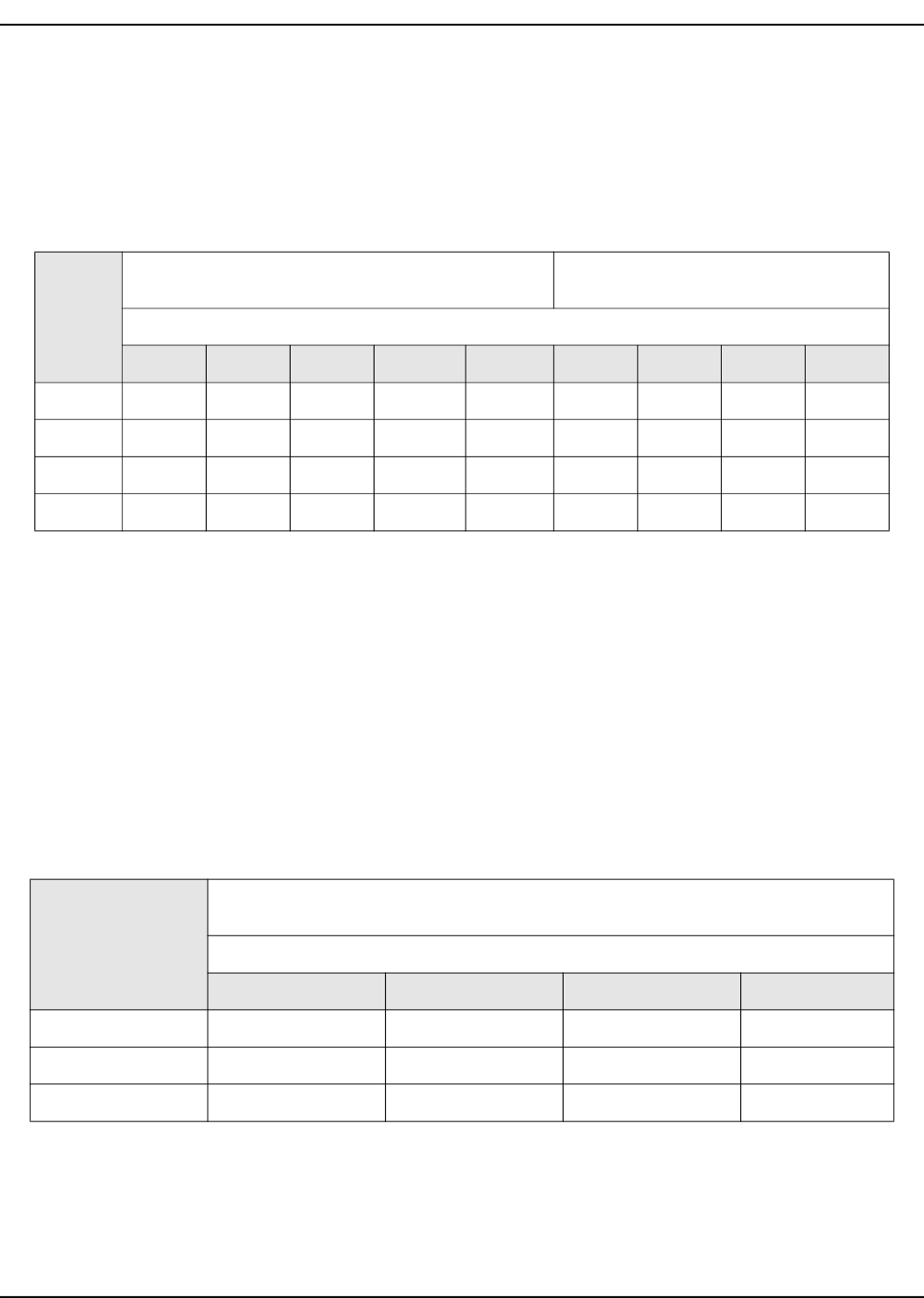
Table 5-1. NG Pipe Sizing
Pipe Size
(in / mm)
For 5–7 in Water Column
(1.24–1.74 kPa)
For 3.5–5 in Water Column
(0.87–1.24 kPa)
Allowable Pipe Distances (ft / m)
0.5 / 13 0.75 / 19 1 / 25 1.25 / 32 1.5 / 38 0.75 / 19 1 / 25 1.25 / 32 1.5 / 38
10 kW 10 / 3.1 60 / 18.3 200 / 61 750 / 228.6 — 20 / 6.1 60 / 18.3 175 / 53.3 —
14/18 kW — 10 / 3.1 55 / 16.7 200 / 60.9 450 / 137.1 — 30 / 9.1 125 / 38.1 200 / 61
20 kW — 10 / 3.1 35 / 10.7 140 / 42.3 300 / 91.4 — 10 / 3.1 60 / 18.3 125 / 38.1
22/24 kW — 10 / 3.1 30 / 9.1 115 / 35.1 250 / 76.2 — 10 / 3.1 60 / 18.3 125 / 38.1
Table 5-2. LP Gas Pipe Sizing
Pipe Size (in / mm)
For 10–12 in Water Column
(2.49–2.99 kPa)
Allowable Pipe Distances (ft / m)
0.5 / 13 0.75 / 19 1 / 25 1.25 / 32
10 kW 30 / 9.1 175 / 53.3 400 / 121.9 —
14/18 kW — 80 / 24.4 350 / 106.7 600 / 182.9
20/22/24 kW — 40 / 12.2 175 / 53.3 550 / 167.6