
Liquid-Cooled Instruction Sheet


Engine Shutdown Add-On Kit 9
Activate Engine Shutdown
Functionality
The controller must detect the installed E-stop and rocker
switch to activate emergency stop functionality.
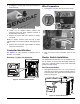
1. Install 7.5A fuse.
2. Connect negative battery terminal and tighten nut.
Verify controller is powered and generator is OFF
3. Disengage E-stop and turn rocker switch ON.
4. Push E-stop knob. Controller should detect that the
E-stop has been engaged and will display
“Emergency Stop Alarm.”
• If alarm appears on controller screen, reset E-stop
by pulling knob and clearing alarm.
• If alarm does not appear on controller screen, E-
stop is not functioning.
Disconnect power and re-check wiring installation.
Contact Generac Technical Support if the problem cannot
be identified or if you need assistance.
5. Repeat steps 1–3 for the rocker switch by toggling
between ON and OFF.
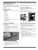
Test Switch Operation—
Protector Diesel
Test E-stop and rocker switch after installation to verify
proper operation.
1. Verify E-stop is disengaged and rocker switch is ON.
2. Press MANUAL key on control panel keypad to start
engine.
3. With engine running, push E-stop knob. Engine
should shut down immediately.
• If engine stops, reset E-stop by pulling knob, clear
alarm on controller, and start engine to verify
generator is operating normally. After verifying
normal operation of E-stop, verify operation of
rocker switch.
• If engine does not stop, either E-stop or rocker
switch is not functioning correctly. Stop generator
through the control panel, and re-check wiring
installation. Contact Generac Technical Support if
the problem cannot be identified or if you need
assistance.
4. Show homeowner how to operate the E-stop and
rocker switch. Remind him or her that these devices
are not intended to be the primary means to shut
down the generator under normal operating
conditions. Accidental activation of an E-stop or
rocker switch will prevent the generator from
operating during a power outage.
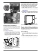
Complete Installation
1. Move main line circuit breaker (generator disconnect)
to ON (closed).
2. Close viewing window.
3. Install side access panel and lock latch using vise-
action key.
Part No. 10000014437 Rev A 5/19/17
©2017 Generac Power Systems, Inc. All rights reserved
Specifications are subject to change without notice.
No reproduction allowed in any form without prior written
consent from Generac Power Systems, Inc.
Generac Power Systems, Inc.
S45 W29290 Hwy. 59
Waukesha, WI 53189
1-888-GENERAC (1-888-436-3722)
www.generac.com