
Liquid-Cooled Instruction Sheet


Engine Shutdown Add-On Kit 7
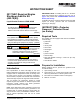
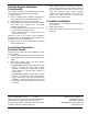
Figure 15 - Wire Preparation with E-Stop Installed
Rocker Switch Installation
The ON/OFF Rocker Switch must be installed so that the
UP position is ON and that the DOWN position is OFF.
Use a continuity tester to verify rocker switch ON position
(normally closed).
Interior Mount Installation
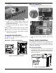
1. See Figure 16. Open viewing window located on
rear enclosure panel. Remove four corner screws
and customer access cover (A). Mark an X on the
outside of the customer access cover centered on
the right side. This will be the center point for the
switch mounting hole.
Figure 16 - Prepare Customer Access Cover
2. Use a step drill to bore a 13/16 in. (21 mm) diameter
hole at the marked location.
IMPORTANT NOTE: Do NOT drill hole larger than 13/16
in. (21 mm)! An oversize hole will prevent rocker
switch installation and cannot be repaired in the field.
The entire customer access cover must be replace
d.
3. Thoroughly clean area of any plastic shavings.
4. Install customer access cover in rear enclosure
panel, securing with four screws.
5. Cut away one square inch (6.5 cm
2
) of insulating
foam on inside of rear panel directly aligned with
rocker switch hole.
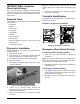
6. See Figure 17. Insert rocker switch (B) into hole from
inboard side of controller access cover. Rocker
switch terminals should be on the insulated side of
the rear enclosure panel.
Figure 17 -
Customer Access Cover Switch Installation
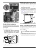
Rocker Switch Wiring Installation
One ON/OFF rocker switch must be wired in series with
the E-Stop harness and then connected to the black wire
on pin side of Deutsch connector.
Switch Wiring
1. Cut one length of 18 AWG wire at 36 in. (91 cm).
Strip 3/8 in. (10 mm) insulation from each end of the
wire.
2. Crimp an insulated quick disconnect connector to
one end of the 36 in. (91 cm) wire.
3. Crimp an insulated quick disconnect connector to the
free end of the black wire from the E-stop harness.
004890
A
004901
x
A
004894
B
004895