
Liquid-Cooled Instruction Sheet


Engine Shutdown Add-On Kit 6
INSTRUCTIONS—Protector
Diesel (with E-stop)
Only one rocker switch is required on Protector diesel
units with an E-stop. The rocker switch will be mounted
inside the customer access cover. Dispose of the second
rocker switch.
Required Tools
The installer must be equipped with common installation
tools including:
• power drill
• drill bits
• center punch
• wire cutters
• wire stripper
• crimper
• pencil or marker
• electrical tape
• Step drill capable of boring a 13/16 inch (21 mm)
diameter hole
• Clear silicone sealant
Prepare for Installation
Before installing this kit, prevent the generator from
accidental startup:
1. Open viewing window.
2. Press OFF key on control panel keypad. Red LED
above key illuminates to confirm system is OFF.
3. Move main circuit breaker switch to OFF (Open).
4. Remove 7.5 A fuse.
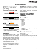
5. See Figure 13. Remove side access panel using
vise-action latch key.
Figure 13 - Remove Side Access Panel
6. Loosen nut on negative battery terminal and
disconnect from post. Verify negative connector is
isolated away from battery.
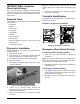
7. Remove six screws with nylon washers to release
rear panel.
NOTE: To simplify removal, rotate left side of panel
outward away from enclosure before disengaging right
side.
8. Remove four screws with nylon washers to release
fascia over control panel.
Controller Identification
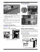
See Figure 14 to verify generator is equipped with an
Evolution 1.0 controller.
Evolution 1.0 (Sync 2.0) Controller
Figure 14 - Evolution 1.0 Controller
Emergency Stop Switch (E-stop)
If an E-stop is NOT already installed:
1. Mount and wire E-stop according to E-stop kit
instructions.
NOTE: Only crimp one black wire from the E-stop to pin
side of Deutsch connector. The other black wire will be
used to connect the rocker switch in series.
2. Complete the additional rocker switch installation as
described below.
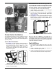
If an E-stop is already installed:
1. See Figure 15. Disconnect one black wire from the
E-stop harness by removing butt splice connector on
pin side of Deutsch connector.
2. Strip 3/8 in. (10 mm) of insulation from each end of
wire (A).
004888
004889