
Liquid-Cooled Instruction Sheet


Engine Shutdown Add-On Kit 4
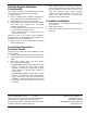
5.
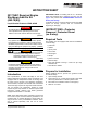
See Figure 8. Connect one crimped end of 24 in. (61
cm) wire (E) and 36 in. (91 cm) wire (C) to rocker
switch terminals on outboard side of controller
access cover. Verify there is enough insulation
removed to properly connect and disconnect wires.
Figure 8 - Crimped Rocker Switch Wires
6.
Position rear enclosure panel close to rear of
generator. Wires connected to switch in rear panel will
be routed and wired to inside of generator control
panel.
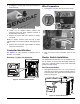
7.
See
Figure 9
. Route loose end of 36 in. (91 cm) wire
(C) along existing harness to left side of control panel.
Figure 9 - Wire Routing
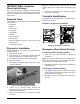
8. See Figure 10. Crimp an insulated barrel splice
crimp connector (F—supplied) to stripped end of 36
in. (91 cm) wire (C). Crimp open end of barrel splice
connector to one of the stripped black wires.
Figure 10 - Crimped Wires at Harness
9. Crimp an insulated barrel splice crimp connector
(G—supplied) to stripped end of 42 in. (106.7 cm)
wire (D). Crimp open end of barrel splice connector
to second stripped black wire.
10. See Figure 9. Route loose end of 42 in. (106.7 cm)
wire (D) up along existing harness to location of
second rocker switch.
11. Guide 42 in. (106.7 cm) wire (D) and 24 in. (61 cm)
wire (E) over the top of connection box divider panel.
Tuck wires between panel flange and roof panel
insulation.
12. Using quick disconnect connectors, fasten two wires
to rocker switch terminals in roof panel.
13. Using four screws with nylon washers, fasten fascia
over control panel.
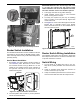
14. See Figure 11. Apply supplied engine shutdown
decals above and next to rocker switches.
Figure 11 - Engine Shutdown Decal
15. Install rear panel.
NOTE: To simplify installation, first engage right side of
panel and then rotate left side in toward enclosure.
Alternately work left and right sides in until slots are
aligned with screw holes on both sides. Avoid pinching
loose switch wires between panel and enclosure. Install
six screws with nylon washers and tighten until snug.
NOTE: Proceed carefully when removing rear enclosure
panel. Gently remove panel, allowing just enough room
to disconnect wires from switch terminals in access
cover. Once wires are disconnected, rear panel may be
fully removed and set aside. Reconnect auxiliary switch
wires before replacing rear panel.
E
C
004896
C
D
E
004897
F
G
C
D
004898
ON
OFF
ENGINE
SHUTDOWN
004899