
Liquid-Cooled Instruction Sheet


Engine Shutdown Add-On Kit 3
2. Use a step drill to bore a 13/16 in. (21 mm) diameter
hole in the roof panel.
IMPORTANT NOTE: Do NOT drill hole larger than 13/16
in. (21 mm)! An oversize hole will prevent rocker
switch installation and cannot be repaired in the field.
The entire roof panel must be replaced.
3. Thoroughly clean area of any metal shavings.
IMPORTANT NOTE: Metal shavings have sharp
edges that can nick, cut, or abrade wire insulation,
possibly resulting in equipment failure.
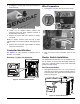
4. See Figure 5. Insert rocker switch (B) into hole and
apply a small amount of silicone sealant around
perimeter for added weather resistance.
Figure 5 - Roof Panel Switch Installation
Interior Mount Installation
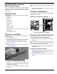
1. See Figure 6. Open viewing window located on rear
enclosure panel. Remove four corner screws and
customer access cover (A). Mark an X on the outside
of the customer access cover centered on the right
side. This will be the center point for the switch
mounting hole.
Figure 6 - Prepare Customer Access Cover
2. Use a step drill to bore a 13/16 in. (21 mm) diameter
hole at the marked location.
IMPORTANT NOTE: Do NOT drill hole larger than 13/16
in. (21 mm)! An oversize hole will prevent rocker
switch installation and cannot be repaired in the field.
The entire customer access cover must be replace
d.
3. Thoroughly clean area of any plastic shavings.
4. Install customer access cover in rear enclosure
panel, securing with four screws.
5. Cut away one square inch (6.5 cm
2
) of insulating
foam on inside of rear panel directly aligned with
rocker switch hole.
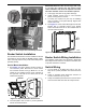
6. See Figure 7. Insert rocker switch (B) into hole from
inboard side of controller access cover. Rocker
switch terminals should be on the insulated side of
the rear enclosure panel.
Figure 7 - Customer Access Cover Switch Installation
Rocker Switch Wiring Installation
The ON/OFF rocker switches must be wired in series and
then connected to the wires alongside the control panel.
Switch Wiring
1. Cut one length of 18 AWG wire at 24 in. (61 cm), one
length of wire at 36 in. (91 cm), and one length of
wire at 42 in. (106.7 cm).
2. Strip 3/8 in. (10 mm) of insulation from each end of all
three wires.
3. Crimp an insulated quick disconnect connector to
one end of the 36 in. (91 cm) and 42 in. (106.7 cm)
lengths of wire.
4. Crimp an insulated quick disconnect connector to
each end of the 24 in. (61 cm) length of wire.
Continued on next page
B
004893
x
A
004894
B
004895