
Liquid-Cooled Instruction Sheet


Engine Shutdown Add-On Kit 2
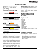
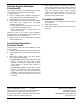
5. See Figure 1. Remove side access panel using vise-
action latch key.
Figure 1 - Remove Side Access Panel
6. Loosen nut on negative battery terminal and
disconnect from post. Verify negative connector is
isolated away from battery.
7. Remove six screws with nylon washers to release
rear panel.
NOTE: To simplify removal, rotate left side of panel
outward away from enclosure before disengaging right
side.
8. Remove four screws with nylon washers to release
fascia over control panel.
Controller Identification
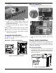
See Figure 2 to verify generator is equipped with an
Evolution 1.0 controller.
Evolution 1.0 (Sync 2.0) Controller
Figure 2 - Evolution 1.0 Controller
Wire Preparation
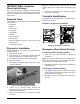
1. See Figure 3. Cut black wire (A) at center of loop.
Figure 3 - Wire Preparation
2. Strip 1/4 inch (6.4 mm) of insulation from cut wire
ends.
Rocker Switch Installation
The ON/OFF Rocker Switches must be installed so that
the UP position is ON and that the DOWN position is
OFF. Use a continuity tester to verify rocker switch ON
position (normally closed).
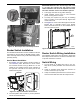
Roof Panel Installation
1. See Figure 4. Measure 5 in. (12.7 cm) in from the
right edge of roof panel, centered vertically. Mark an
X at this location. This will be the center point for the
switch mounting hole.
Figure 4 - Prepare Roof Panel
004888
004889
004890
A
004891
x
004892