MODEL: 005982-0 Owner's Manual GP 3250 Portable Generator
Table of Contents Owner's Manual Introduction....................................................................................... 1 Read this Manual Thoroughly ........................................................... 1 Safety Rules ..................................................................................... 2 Standards Index ..................................................................... 3 General Information ..........................................................................
Introduction INTRODUCTION Thank you for purchasing this model by Generac Power Systems, Inc. This model is a compact, high performance, air-cooled, engine driven generator designed to supply electrical power to operate electrical loads where no utility power is available or in place of utility due to a power outage. READ THIS MANUAL THOROUGHLY If any portion of this manual is not understood, contact the nearest Authorized Dealer for starting, operating and servicing procedures.
Safety Rules • Do not insert objects through unit’s cooling slots. • When working on this equipment, remain alert at all times. Never work on the equipment when physically or mentally fatigued. • Never use the generator or any of its parts as a step. Stepping on the unit can stress and break parts, and may result in dangerous operating conditions from leaking exhaust gases, fuel leakage, oil leakage, etc. NOTE: This generator is equipped with a spark arrestor muffler.
Safety Rules STANDARDS INDEX In the absence of pertinent standards, codes, regulations and laws, the published information listed below may be used as a guideline for operation of this equipment. Always reference the latest revision available for the standards listed. 1. NFPA No. 70, NFPA HANDBOOK OF NATIONAL ELECTRIC CODE. 2. Article X, NATIONAL BUILDING CODE, available from the American Insurance Association, 85 John Street, New York, N.Y. 10038. 3.
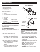
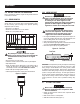
General Information 1.1 UNPACKING Figure 1 – Wheel Assembly • Remove all packaging material. • Remove separate accessory box. • Remove the generator from carton. 1.1.1 ACCESSORY BOX Check all contents. If any parts are missing or damaged, locate an authorized dealer at 1-888-436-3722. • • • • • • • • 1 - Owner’s manual 1 - Oil SAE 30 3 - Product Registration Cards (English, Spanish, French) 2 - 8” WHEELS 1 - Axle 1 - Frame Foot 1 - Handle with grip 1 - Hardware Bag 1 - Plastic Spacer 2 - M8-1.
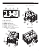
Operation Figure 3 - Control Panel 9. 10. 11. 12. 13. 14. 15. 16. 17. Muffler – Quiets the engine. Handle – Pivot and retract for storage. Gas Cap – Fuel fill location. Fuel Gauge – Shows fuel level in tank. Oil Check/Fill – Check and fill oil here. Recoil Starter – Use to start engine manually. Fuel Shut Off – Valve between fuel tank and carburetor. Oil Drain Plug – Used to drain engine oil. Spark Arrestor – Reduces fire hazard by containing sparks.
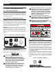
Operation 2.2 CORD SETS AND CONNECTION PLUGS 2.2.1 120 VAC DUPLEX RECEPTACLE This is a 120 Volt outlet protected against overload by a 14 Amp circuit breaker (Figure 7). 14 Amps of current may be drawn from each socket, however, total power drawn must be kept within data plate ratings. Use only high quality, well insulated, 3-wire grounded cord sets rated for 125 Volts at 20 Amps (or greater). 2.2.
Operation 2.3.2 CONNECTING ELECTRICAL LOADS DO NOT connect 240 Volt loads to 120 Volt receptacles. DO NOT connect 3-phase loads to the generator. DO NOT connect 50 Hz loads to the generator. • Let engine stabilize and warm up for a few minutes after starting. • Plug in and turn on the desired 120 or 240 Volt AC, single phase, 60 Hz electrical loads. • Add up the rated watts (or amps) of all loads to be connected at one time.
Operation 2.6 BEFORE STARTING THE GENERATOR Prior to operating the generator, engine oil and gasoline will need to be added, as follows: 2.6.1 ADDING ENGINE OIL All oil should meet minimum American Petroleum Institute (API) Service Class SJ, SL or better. Use no special additives. Select the oil's viscosity grade according to the expected operating temperature (also see chart).
Maintenance • Turn engine ON/OFF switch to ON position (Figure 11). • Move engine CHOKE lever to the FULL CHOKE position (Figure 11). • To start engine, firmly grasp the recoil handle and pull slowly until increased resistance is felt. Pull rapidly up and away. • When engine starts, move choke lever to 1/2-CHOKE position until engine runs smoothly and then fully into RUN position. If engine falters, move choke back out to 1/2-CHOKE position until engine runs smoothly and then to RUN position.
Maintenance 3.3 GENERAL RECOMMENDATIONS 3.3.3 ENGINE MAINTENANCE The warranty of the generator does not cover items that have been subjected to operator abuse or negligence. To receive full value from the warranty, the operator must maintain the generator as instructed in this manual. disconnect the spark plug wire from spark Some adjustments will need to be made periodically to properly maintain the generator.
Maintenance 3.3.6 REPLACING THE SPARK PLUG 3.4 SERVICE AIR FILTER Use spark plug F6TC, NGK BP6IS or Champioin RN11YC. Replace the plug once each year. This will help the engine start easier and run better. The engine will not run properly and may be damaged if using a dirty air filter. Clean the air filter every 25 hours (Figure 15). Clean or replace more often if operating under dusty conditions. 1. Stop the engine and pull the spark plug wire off of the spark plug. 2.
Maintenance 3.7 LONG TERM STORAGE 3.8 OTHER STORAGE TIPS It is important to prevent gum deposits from forming in essential fuel system parts such as the carburetor, fuel hose or tank during storage. Also, experience indicates that alcohol-blended fuels (called gasohol, ethanol or methanol) can attract moisture, which leads to separation and formation of acids during storage. Acidic gas can damage the fuel system of an engine while in storage. • Do not store gasoline from one season to another.
Troubleshooting 4.1 TROUBLESHOOTING GUIDE PROBLEM CAUSE CORRECTION Engine is running, but no AC output is available. 1. 2. 3. 4. Circuit breaker is open. Poor connection or defective cord set. Connected device is bad. Fault in generator. 1. 2. 3. 4. Reset circuit breaker. Check and repair. Connect another device that is in good condition. Contact Authorized Service Facility. Engine runs good but bogs down when loads are connected. 1. 2. 3. 4. Short circuit in a connected load.
Notes 14
Notes 15
Warranty FEDERAL EMISSION CONTROL WARRANTY STATEMENT YOUR WARRANTY RIGHTS AND OBLIGATIONS The United States Environmental Protection Agency (EPA) and Generac Power Systems, Inc. (Generac) are pleased to explain the Emission Control System warranty on your new 2008 and later equipment. New equipment that use small spark-ignited engines must be designed, built, and equipped to meet stringent anti-smog standards for the federal government.
Warranty EMISSION CONTROL SYSTEM WARRANTY Emission Control System Warranty (ECS warranty) for equipment using small spark-ignited engines: (a) Applicability: This warranty shall apply to equipment that uses small off-road engines. The ECS Warranty period shall begin on the date the new equipment is purchased by/delivered to its original, end-use purchaser/owner and shall continue for 24 consecutive months thereafter.
Warranty GENERAC POWER SYSTEMS “TWO YEAR” LIMITED WARRANTY FOR GP SERIES PORTABLE GENERATORS For a period of two years from the date of original sale, Generac Power Systems, Inc. (Generac) warrants its GP Series generators will be free from defects in materials and workmanship for the items and period set forth below. Generac will, at its option, repair or replace any part which, upon examination, inspection and testing by Generac or a Generac Authorized Warranty Service Dealer, is found to be defective.