® CENTURION Owner’s Manual Liquid-cooled, Prepackaged Standby Generators Models: 004912-0, 004912-1 (15 kW LP/15 kW Natural Gas) 120/240V Single-phase w/ 100 Amp Transfer Switch 004913-0, 004913-1, 004913-2 (25 kW LP/25 kW Natural Gas) 120/240V Single-phase w/ 200 Amp Transfer Switch *This manual should remain with the unit. DANGER ONLY QUALIFIED ELECTRICIANS OR CONTRACTORS SHOULD ATTEMPT INSTALLATION!! DEADLY EXHAUST FUMES.
INTRODUCTION Thank you for purchasing this model of the standby generator product line by Generac Power Systems. Every effort was expended to make sure that the information and instructions in this manual are both accurate and current at the time the manual was written. However, the manufacturer reserves the right to change, alter or otherwise improve this product(s) at any time without prior notice.
Table of Contents Centurion Liquid-cooled 15 kW and 25 kW Generators Introduction ................................Inside Front Cover Read This Manual Thoroughly ............................IFC Operation and Maintenance ................................IFC How to Obtain Service..........................................IFC Authorized Dealer Locator Number ........................IFC Section 3 — OPERATION..........................13 3.1 3.2 Safety Rules .......................................................
IMPORTANT SAFETY INSTRUCTIONS Guardian Liquid-cooled 15 kW, 20 kW and 25 kW Generators ! SAVE THESE INSTRUCTIONS – The manufacturer suggests that these rules for safe operation be copied and posted in potential hazard areas. Safety should be stressed to all operators, potential operators, and service and repair technicians for this equipment. ! SAVE THESE INSTRUCTIONS – This manual contains important instructions that should be followed during installation and maintenance of the generator and batteries.
Important Safety Instructions Centurion Liquid-cooled 15 kW and 25 kW Generators • Before performing any maintenance on the generator, disconnect its battery cables to prevent accidental start-up. Disconnect the cable from the battery post indicated by a NEGATIVE, NEG or (–) first. Reconnect that cable last. • Never use the generator or any of its parts as a step.
Section 1 - General Information Centurion Liquid-cooled 15 kW and 25 kW Generators 1.1 GENERATOR 1.3 AUTOMATIC SYSTEM OPERATION This equipment is a liquid-cooled, engine-driven generator set. The generator is designed to supply electrical power that operates critical electrical loads during utility power failure. The unit has been factory-installed in a weather resistant, all metal enclosure and is intended for outdoor installation only.
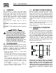
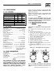
Section 1 - General Information Centurion Liquid-cooled 15 kW and 25 kW Generators Figure 1.2 - Main Circuit Breaker 1.5 Model Rating Phase 04912 04913 15,000 25,000 1 1 Actual Current C/B Rating* 62.5 104.2 * Amp Rating of CB structured under model. MAIN CIRCUIT BREAKER 70 125 Circuit Breaker 70A BQ2 125A BQ2 Figure 1.3 - Engine Protective Devices The generator’s main circuit breaker is included with the unit. The breaker for each unit is described in Figure 1.2. 1.
Section 1 — General Information Centurion Liquid-cooled 15 kW and 25 kW Generators Figure 1.5- High Coolant Temperature Switch 1.7.3 1.7.5 • LED 1 is RED. The LED will be on when utility sensing is NOT available to the circuit board. This LED will function only when the AUTO/OFF/ MANUAL switch is set in the Auto position. • LED 2 is YELLOW. This LED will be on when the circuit board battery charger is on. This LED will cycle on and off with the battery charger, 4.85 hours on the 4.85 hours off.
Section 1 — General Information Centurion Liquid-cooled 15 kW and 25 kW Generators Fuel pressure for a natural gas set up should be five inches to 14 inches of water column (0.18 to 0.5 psi) at all load ranges. 1.10 SPECIFICATIONS 1.10.1 GENERATOR Model Rated Max. Cont. AC Power Output (kW) Rated voltage (volts) No.
Section 2 — Installation Centurion Liquid-cooled 15 kW and 25 kW Generators DANGER ! Serious injury or damage may occur if not configured properly. Please consult an authorized Generac Service Dealer with any questions. 1.16 BEFORE INSTALLATION Before installing this equipment, check the ratings of both the generator and the transfer switch. Read “Emergency Isolation Method” and “Total Circuit Isolation Method” in the installation manual (Part No. 079699). 1.
Section 2 — Installation Centurion Liquid-cooled 15 kW and 25 kW Generators NOTE: For more information about the installation of a standby system, you can order Engine-Generator Standby Electric Power Systems Installer’s Guide and Reference Manual (part #046622) from a Generac Authorized Service Dealer. 2.1.
Section 2 — Installation Centurion Liquid-cooled 15 kW and 25 kW Generators Figure 2.1 – Basic Standby Electric System 2.6 TOTAL CIRCUIT ISOLATION METHOD When a generator capable of powering all electrical loads in the circuit is to be installed, use the “Total Circuit Isolation Method.” It is possible for the generator to be overloaded when this isolation method is employed. The following apply to the transfer switch in this type of system.
Section 2 — Installation Centurion Liquid-cooled 15 kW and 25 kW Generators 2.8 GENERATOR AC NEUTRAL CONNECTIONS Generac uses an UNGROUNDED AC neutral. Grounding is recommended only at the main service entrance. If the neutral wire is grounded and one of the phase loads becomes grounded, the excessive current opens the load circuit breaker or collapses the generator field. The actual result depends on the electrical characteristics of the particular installed generator. 2.
Section 2 — Installation Centurion Liquid-cooled 15 kW and 25 kW Generators When using maintenance-free batteries, it is not necessary to check the specific gravity or electrolyte level. Have these procedures performed at the intervals specified in Section 4, “Maintenance.” A negative ground system is used. Battery connections are shown on the wiring diagrams. Make sure all batteries are correctly connected and terminals are tight. Observe battery polarity when connecting batteries to the generator set.
Section 3 - Operation Centurion Liquid-cooled 15 kW and 25 kW Generators 3.1 USING A STANDARD “GTS” TRANSFER SWITCH When required, the pre-packaged standby generator can be installed with an engineered Generac “GTS” type engineered automatic transfer switch. When a GTS type transfer switch is used, it controls automatic operation and automatic transfer as follows: • Solid state circuits in the transfer switch monitor utility power source voltage.
Section 3 - Operation Centurion Liquid-cooled 15 kW and 25 kW Generators 3.2.5 7.5 AMP IN-LINE FUSE This in-line fuse is connected in wire 15A which runs between the AUTO/OFF/MANUAL switch and position 10 of the 076009A PCB. This fuse protects the start, fuel, field boost, and transfer outputs from the PCB and will open if there is excessive current draw on any one of these outputs.
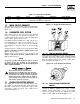
Section 4 — Maintenance Centurion Liquid-cooled 15 kW and 25 kW Generators Figure 3.3 - Engine Block Heater F. EVERY 800 OPERATING HOURS 1. Retorque cylinder head. (See Section 1.13, “Torque Specs”.) 2. Retorque intake and exhaust manifold. (See Section 1.13, “Torque Specs”.) 3. Check engine compression. 4. Check valve clearance. 4.2 COOLING SYSTEM Air intake and outlet openings in the generator compartment must be open and unobstructed for continued proper operation.
Section 4 — Maintenance Centurion Liquid-cooled 15 kW and 25 kW Generators Figure 4.1 - Oil Dipstick and Oil Fill Cap OIL DIPSTICK 4.5.4 INSPECT COOLING SYSTEM • Inspect engine cooling system at least once each month. • Check hoses for damage, deterioration, leaks, etc. Correct any discrepancies found. • Check hose clamps for tightness. • Check fluid levels as outlined above. 4.5.5 PERFORM VISUAL INSPECTION Complete a thorough visual inspection of the entire generator monthly.
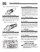
Section 4 — Maintenance Centurion Liquid-cooled 15 kW and 25 kW Generators 1. Remove OIL DRAIN HOSE from its retaining clip. 2. Loosen and remove OIL DRAIN HOSE CAP. Drain oil completely into suitable container. 3. When all oil has drained, install and tighten OIL DRAIN HOSE CAP, and re-install into its retaining clip. 4. Turn OIL FILTER (Figure 4.2) counterclockwise and remove. Dispose of old filter. 5. Apply light coating of new engine oil to seal of new oil filter.
Section 4 — Maintenance Centurion Liquid-cooled 15 kW and 25 kW Generators Once each year, have the generator cleaned and inspected by an Authorized Service Dealer. That dealer will use dry, low pressure air to clean internal windings. Parts inside the control console should be cleaned and inspected at this time as well. DANGER Finally, have the insulation resistance of stator and rotor windings checked. If insulation resistances are excessively low, the generator may require drying. 4.6.
Section 4 — Maintenance Centurion Liquid-cooled 15 kW and 25 kW Generators 1. The base frame of the unit contains an optional fuel inlet location that is capped at the factory. Check that it is secured in place. The same applies for any access ports in the roof of the enclosure. If any of these caps are missing, contact a Generac Authorized Dealer. 2. Inside the generator set, the chance of rodent entry into the control panel is greatly reduced by the inclusion of adjustable wire connectors.
Section 4 — Maintenance Centurion Liquid-cooled 15 kW and 25 kW Generators 4.9 SCHEDULED MAINTENANCE The following is a recommended maintenance schedule for Centurion small standby and residential generator sets. The established intervals in the schedule are the maximum recommended when the unit is used in an average service application. They will need to be decreased (performed more frequently) if the unit is used in a severe application.
Section 4 — Maintenance Centurion Liquid-cooled 15 kW and 25 kW Generators Maintenance Tasks Level 1 Recommended to be done monthly/ 10 hrs. Level 2 Task Comp. (DateInitials) Required to be done 3 months/ Break-in 30 hrs. Level 3 Task Comp. (DateInitials) Required to be done Semiannually/ 50 hrs. Level 4 Task Comp. (DateInitials) Required to be done Annually/ 100 hrs. Task Comp. (DateInitials) 1. Disable the unit from operating per the first page warning. 2. Check the engine oil level.
Section 4 — Maintenance Centurion Liquid-cooled 15 kW and 25 kW Generators Maintenance Tasks Level 1 Recommended to be done monthly/ 10 hrs. 13. Initiate an automatic start and transfer of the unit to site load and exercise it for at least one hour looking for leaks, loose connections or components, and abnormal operating conditions. Correct as necessary. 14.
Section 5 — Troubleshooting Centurion Liquid-cooled 15 kW and 25 kW Generators 5.1 TROUBLESHOOTING POINTS PROBLEM CAUSE CORRECTION Engine won’t crank. 1. 15 amp fuse blown. 2. Loose or corroded or defective battery cables. 3. Defective starter contactor. 4. Defective starter motor. 5. Dead or Defective Battery. 1. Replace fuse. 2. Tighten, clean or replace battery cables as necessary. 3. Replace contactor. 4. Replace starter motor. 5. Remove, change or replace battery.
Section 6 — Notes Centurion Liquid-cooled 15 kW and 25 kW Generators 24 Generac® Power Systems, Inc.
Section 7 - Installation Diagram Centurion Liquid-cooled 15 kW and 25 kW Generators Drawing No. 0E1533-A Generac® Power Systems, Inc.
(BLACK) (BLACK) (BLUE) (RED) BLUE 178 225A 239 178 225 BLUE 0 225A 15A 178 239 183 4 TR1 YELLOW 8 F1 15C 15C BLUE 14 15 14 15 0 183 162 CB2 162 BLACK BLACK 15C 2 0 4 0 4 15E 6 14 AS - FO SW 23 194 0 S16 14 S16 94 23 85 TS2 CAP 0 0 0 13 14 13 4 229 14 229 S16 S15 SUPRESSION ASSEMBLY FUSE 15 AMPS 56 56 BLUE 85 85 85 TERMINAL STRIP 7 POS.
Section 8 - Electrical Data Centurion Liquid-cooled 15 kW and 25 kW Generators Wiring Diagram — 1.5L Engine — Drawing No.
EC 28 Generac® Power Systems, Inc.
Section 8 - Electrical Data Centurion Liquid-cooled 15 kW and 25 kW Generators Electrical Schematic — 1.5L — Drawing No.
Section 9 - Exploded Views and Parts Centurion Liquid-cooled 15 kW and 25 kW Generators Governor Assembly — Drawing No. 0E1331-B 5 4 3 ITEM (13) NEOPRENE COATING 2 1 14 6 7 10 WIRE HARNESS 15 12 9 7 16 "A" 17 TO "A" 10 7 CARBURETOR ARM (REF.) 6 INTAKE MANIFOLD (REF.) 11 ITEM 1 2 3 4 5 6 7 8 9 10 11 12 13 14 15 16 17 18 PART NO. 098290 098941A 098958A 098942A 098225 043146 022097 084543A 098783 037398 0E1326 0A7106 074031 029333A 022507 022473 064526 0E1694 QTY.
Section 9 - Exploded Views and Parts Centurion Liquid-cooled 15 kW and 25 kW Generators Mounting Base — Drawing No. 0E0768-B 8 7 6 14 5 13 7 6 4 9 15 15 20 10 17 5 7 6 7 6 11 18 19 16 2 3 9 10 1 ITEM 1 2 3 4 5 6 7 8 9 10 11 13 14 15 16 17 18 19 20 21 PART NO. 0D8656 027482 070936 070936C 039253 022145 022129 045771 071956 051730 021991 0D9335 0D9336 0C2454 047411 022097 022473 055414 049813 026850 QTY. 1 2 2 2 8 12 16 4 4 4 1 2 2 12 1 1 1 1 1 1 DESCRIPTION BASE,MOUNTING 1.
Section 9 - Exploded Views and Parts Centurion Liquid-cooled 15 kW Generator Standard Compartment — Drawing No. 0E0771-E 21 WELD STUD UNDER ROOF PANEL FOR ACCESS COVER E 1 11 13 14 4 "Y" 26 10 11 2 15 29 22 23 26 10 17 11 18 15 8 24 11 11 4 5 9 26 15 26 17 10 6 19 25 26 24 3 19 10 5 7 24 11 32 Generac® Power Systems, Inc. 17 NOTE: USE DOOR LATCH FASTENER TO SECURE GROUND WIRE. NOTE: USE LOCTITE ON NUTS ITEM #26.
Section 9 - Exploded Views and Parts Centurion Liquid-cooled 15 kW Generator Standard Compartment — Drawing No. 0E0771-E ITEM 1 2 3 4 5 6 7 8 9 10 11 12 13 14 15 16 17 18 19 20 21 22 23 24 25 26 27 28 29 PART NO. 0D8666 0D8664C 0D8657 0D8660 0A7568 0D8659 0D8662 0D8661 0D8658 067042 0C2454 033530 051716 022152 0912970064 023762 0912970063 022264 067035 022127 0C2634A 022473 022097 0D2023 0F3390 037337 0D2023 0D8664A 0D8664B QTY.
34 Generac® Power Systems, Inc. 36 9 43 38 8 10 4 45 39 7 18 42 19 6 1 22 23 11 24 3 35 10 14 4 10 "Y" "Y" 15 26 18 32 19 17 11 11 17 5 15 34 1 21 29 31 10 42 24 22 23 3 40 11 28 4 48 25 46 30 2 20 STATES FOAM IS ON FAR SIDE STATES FOAM IS ON NEAR SIDE 11 NOTE: USE DOOR LATCH 17 NOTE: USE LOCTITE ON NUT #037337. TYPICAL OF FRONT DUCT & ROOF PANEL. SECURE AS SHOWN.
Section 9 - Exploded Views and Parts Centurion Liquid-cooled 25 kW Generator Acoustic Compartment — Drawing No. 0E0772-G ITEM 1 2 3 4 5 6 7 8 9 10 11 12 13 14 15 16 17 18 19 20 21 22 23 24 25 26 27 28 29 30 31 32 33 34 35 36 37 38 39 40 41 42 43 45 46 47 48 PART NO.
Section 9 - Exploded Views and Parts 39 32 27 25 26 33 6 10 7 8 58 31 5 55 54 9 53 52 3 TO 'A' 50 34 42 38 39 49 40 41 12 28 11 2 30 31 36 Generac® Power Systems, Inc. 57 17 28 18 28 26 16 51 13 29 38 A 23 39 24 'A' 40 41 21 28 14 56 22 35 20 1 28 43 15 45 46 44 47 32 37 36 40 41 48 4 Centurion Liquid-cooled 15 kW and 25 kW Generators Control Panel — Drawing No.
Section 9 - Exploded Views and Parts Centurion Liquid-cooled 15 kW and 25 kW Generators Control Panel — Drawing No. 0E0778-G ITEM PART NO. QTY.
6 38 Generac® Power Systems, Inc. 8 7 2 9 10 5 11 12 24 4 13 14 39 10 15 1 24 32 41 16 30 72 14 1 10 9 24 35 34 33 11 45 10 44 11 14 19 10 24 36 17 11 20 10 11 14 12 47 17 26 46 18 11 49 71 14 10 21 20 70 11 57 22 6 24 25 69 67 56 55 59 58 63 65 64 52 61 7 WATERPUMP HARDWARE 62 60 Section 9 - Exploded Views and Parts Centurion Liquid-cooled 15 kW and 25 kW Generators Engine — Drawing No.
Section 9 - Exploded Views and Parts Centurion Liquid-cooled 15 kW and 25 kW Generators Engine — Drawing No. 0E1228-E ITEM PART NO. QTY.
28 22 40 Generac® Power Systems, Inc. 32 28 "A" 30 29 (BOTTOM ONLY) 1 10 2 21 9 32 31 23 26 35 10 8 8 8 8 3 14 12 12 24 18 TO THERMOSTAT ADAPTER 14 WATER INLET TUBE (ON BLOCK) 19 20 7 33 34 TO WATER INLET (MIDWAY UP ENGINE BLOCK) 7 16 7 TO ENGINE BYPASS 4 15 17 6 13 17 14 11 34 33 12 11 Section 9 - Exploded Views and Parts Centurion Liquid-cooled 15 kW and 25 kW Generators Radiator — Drawing No.
Section 9 - Exploded Views and Parts Centurion Liquid-cooled 15 kW and 25 kW Generators Radiator — Drawing No. 0E0769-H ITEM 1 2 3 4* 5 6 7 8 9 10 11 12 13 14 15 16 17 * 18 19 20 21 22 23 24 26 27 28 29 30 31 32 33 34 35 PART NO. 0D8657 0A5734 0A6237 0A6238 084918 051520N 048031C 099502 083709 052250 047411 022097 049813 022473 084427 051520Z 075443 056892 0A6284 0A6258 029032 031669 060035 022127 046627 0C7649 0C2454 076749 0E0726 035461 0A7275 0A2111 065852 047290A QTY.
Section 9 - Exploded Views and Parts Centurion Liquid-cooled 15 kW and 25 kW Generators Fuel System — Drawing No. 0E0774-D 18 13 21 24 25 8 22 17 16 29 "C" 14 30 12 34 31 36 37 35 32 33 38 39 19 40 41 26 20 6 28 PORT "OUT 1" (NATURAL GAS) 41 3 6 11 43 9 14 10 42 "D" 23 40 41 6 PORT "OUT 2" 2 11 15 4 L.P. VAPOR 42 Generac® Power Systems, Inc.
Section 9 - Exploded Views and Parts Centurion Liquid-cooled 15 kW and 25 kW Generators Fuel System — Drawing No. 0E0774-D ITEM PART NO.
Section 9 - Exploded Views and Parts 14 15 2 18 9 To Blower Housing 8 36 32 24 1 23 35 17 7 13 16 29 28 33 22 10 30 21 3 31 12 21 20 19 6 5 4 26 To Engine Crankshaft Centurion Liquid-cooled 15 kW and 25 kW Generators Alternator — Drawing No. 0A9348-F 44 Generac® Power Systems, Inc.
Section 9 - Exploded Views and Parts Centurion Liquid-cooled 15 kW and 25 kW Generators Alternator — Drawing No. 0A9348-F ITEM 1 2 3 4 5 6 7 8 9 10 11 12 13 14 15 16 17 18 19 20 21 22 23 24 26 * 27 28 29 30 31 32 33 35 36 PART NO.
Section 9 - Exploded Views and Parts Centurion Liquid-cooled 15 kW and 25 kW Generators Battery — Drawing No. 0E0770-A 2 STARTER SOLENOID 8 13 4 14 8 3 1 TO ENGINE BLOCK 16 6 5 7 9 15 ITEM 1 2 3 4 5 6 7 8 9 13 14 15 16 17 PART NO. 077483 038804D 038805B 0742600131 022131 046526 052213 075763 0D8668 050331A 050331 0C2454 025507 027482 QTY. 1 1 1 1 1 1 1 3 1 1 1 2 1 2 DESCRIPTION BATT 12VDC 75-AH 26 CABLE BATT RED #4 X 20.00 CABLE BATT BLK #4 X 23.00 ASSY,WIRE#16 RED 1.
Section 9 - Exploded Views and Parts Centurion Liquid-cooled 15 kW and 25 kW Generators Muffler — Drawing No. 0E0773-A 10 9 14 8 15 6 12 13 9 3 7 3 5 4 3 2 ITEM 1 2 3 4 5 6 7 8 9 10 11 12 13 14 15 PART NO. 0A4355 0E2844 036434 036449 0E0109 0C1318 0D8657 0E0170 0D9437 060366 039253 022145 022129 045771 0A8974 027837 QTY. 1 1 3 3 1 1 1 1 1 2 4 4 4 4 1 2 DESCRIPTION MANIFOLD EXHAUST 1.5L NIPPLE TOE 1.5NPTX5.5 BLK IRON BOLT U 5/16-18 X 2.09 SADDLE 2 INCH PIPE,EXHAUST 1.
Section 10 – Warranty Centurion Liquid-cooled 15 kW and 25 kW Generators CALIFORNIA EMISSION CONTROL WARRANTY STATEMENT YOUR WARRANTY RIGHTS AND OBLIGATIONS The California Air Resources Board (CARB) and Generac Power Systems, Inc. (Generac) are pleased to explain the Emission Control System Warranty on your new engine.* In California, new utility, and lawn and garden equipment engines must be designed, built and equipped to meet the state’s stringent anti-smog standards.
Section 10 – Warranty Centurion Liquid-cooled 15 kW and 25 kW Generators EMISSION CONTROL SYSTEM WARRANTY Emission Control System Warranty (ECS Warranty) for 1995 and later model year engines: (a) Applicability: This warranty shall apply to 1995 and later model year engines. The ECS Warranty Period shall begin on the date the new engine or equipment is purchased by/delivered to its original, end-use purchaser/owner and shall continue for 24 consecutive months thereafter.
Section 10 – Warranty Centurion Liquid-cooled 15 kW and 25 kW Generators GENERAC POWER SYSTEMS "TWO YEAR" LIMITED WARRANTY FOR CENTURION "PREPACKAGED EMERGENCY AUTOMATIC STANDBY GENERATORS" For a period of two years from the date of original sale, Generac Power Systems, Inc.