
Install Manual

Installing Generac PWRcell Battery
20 Installation Manual for Generac PWRcell Battery
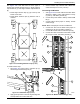
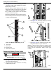
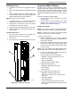
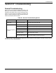
7. See Figure 4-19. Continue connecting the remain-
ing battery modules. While installing CAT5 cables:
• Work from top to bottom
• Connect battery modules sharing a shelf with a
black jumper cable (I) going from the rear battery
COM OUT port to the front battery COM IN port
• Do not install a CAT5 cable to the last battery
module’s COM OUT port (M)
• Remaining COM cables can be left disconnected.
• Unused CAT5 jumpers should be kept in safe place
for future module upgrades.
I
009941
M
L
K
J
I
Figure 4-19. Module COM Cabling (2 of 2)
I Gray CAT5
J Blue CAT5
K Orange CAT5
L Black CAT5 Jumpers
Connecting Battery Power Cable
Electrocution. Never reach into port or touch
battery terminals with hands or tools. Doing so
will result in death, serious injury, equipment or
property damage.
DANGER
(000639)
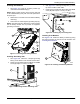
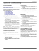
1. See Figure 4-20. Remove gray rubber cap (A)
from each module power port.
2. Plug black power cable connectors into battery
module power ports (B).
A
B
Figure 4-20. Power Cable Ports
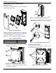
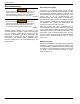
3. See Figure 4-21. Install loop jumper (C) on every
unused power cord connector (D).
009943
C
D
Figure 4-21. Installing Loop Jumper
4. See Figure 4-22. Tie unused loop jumpers (E) to
wiring chase baffle slot (F) for future use.
NOTE: If a battery module needs to be replaced, spare
loop jumpers can be used to keep the PWRcell battery
running until the replacement battery module gets
installed.
E
F
009944
Figure 4-22. Unused Loop Jumpers