
Install Manual

Installing Generac PWRcell Battery
16 Installation Manual for Generac PWRcell Battery
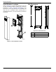
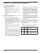
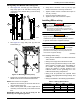
To install REbus wiring:
1. See Figure 4-4. Install REbus conductors to their
terminal blocks: RE+ to red (A), RE- to blue (B).
2. Install equipment grounding conductor to green ter-
minal block (C).
3. If required, route field wiring conductors through
the grommet wiring chase baffle (D).
NOTE: Do not route wires around the baffle.
4. At the PWRcell inverter, install RE+ and RE- con-
ductors to any unused 30A REbus DC disconnect.
5. Secure equipment grounding conductor to the
PWRcell inverter ground bar.
A
C
B
D
009928
Figure 4-4. REbus Wiring
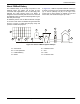
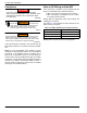
Connecting Blackstart Battery
See Figure 4-5. Connect blackstart battery lead to bat-
tery terminal (E).
NOTE: One lead is already connected to terminal (F).
F
009928
E
Figure 4-5. Blackstart Battery Connections
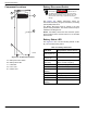
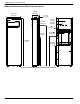
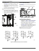
Installing Battery Modules
• Record battery module serial numbers prior to
installation in Table 1: Important Information
located in the inside front cover of this manual.
• When installing battery modules, install top, rear
module first, regardless of configuration.
• See Figure 4-6 for the order of battery module and
spacer installation for PWRcell 9 (B), PWRcell 12
(C), PWRcell 15 (D), and PWRcell 17 (E).
NOTE: Module spacers (F) are required on
PWRcell 9 (B) and 15 (D) configurations.
1
3
2
4
1
3
2
4
1
3
5
2
4
6
1
3
5
2
4
6
009899
E
D
C
B
F
F
Figure 4-6. Battery Module/Spacer Order of Installation