
Install Manual

10 Installation Manual for Generac PWRcell Battery
General Information
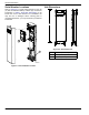
Component Locations
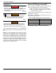
ON
OFF
BATTERY DISCONNECT
0009890
C
D
E
B
A
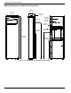
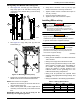
Figure 2-4. Component Locations
A Battery disconnect switch
B Battery status LED
C Intake filter
D Front cover
E Exhaust vent
Battery Disconnect Switch
(000600)
Electrocution. Initiate a system-wide shutdown and turn
the PWRcell Disconnect Switch OFF on all connected
batteries before performing service. Failure to do so will
result in death, serious injury, equipment and property
damage.
DANGER
See Figure 2-4. Battery Disconnect switch (A)
disconnects the battery string from the battery monitoring
system (BMS) electronics.
The Battery Disconnect must be locked in the OFF
position during installation. The switch bracket accepts a
standard lockout/tagout lock.
NOTE: Turn Battery Disconnect OFF whenever system
will be powered down and left inactive for an extended
period of time.
Battery Status LED
See Figure 2-4. The color and strobing interval of LED
(B) communicates battery status.
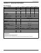
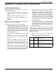
Table 2-1. Battery Status LED
LED State Interpretation (strobe interval)
Green, 3 sec
solid at power up
Enabled, operation starting
Red, 3 sec solid
at power up
Disabled
Red/green,
alternating
Initializing, connecting battery and
REbus, system energizing
Green, solid Enabled, charging
Green, strobe Enabled, standby (3 sec)
Green, rapid
flashing
Enabled, discharging
Orange, solid Waiting
Orange, strobe Asleep (8 sec)
Red, strobe Disabled (3 sec)
Red, rapid
flashing
Error state