
Install Manual

Control Panel Startup / Testing
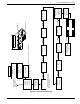
Installation Guidelines For Spark-Ignited Stationary Generators 39
Operational Checks
NOTE: The following procedures require special tools
and skills. Contact a Generac dealer or an IASD to per-
form these tasks.
Electrical Checks
NOTE: Verify all power and control wiring is correctly ter-
minated in the generator and corresponding location in
transfer switch. For three-phase applications, verify gen-
erator phase rotation matches utility phase rotation L1-
L2-L3 or L3-L2-L1. Validate phase rotation L1-L2-L3 or
L3-L2-L1 with an phase rotation tester (if three-phase).
NOTE: To correct phase rotation, interchange any two
leads.
Proceed as follows to complete electrical checks:
1. Verify generator is in OFF mode. Red LED above
OFF on control panel illuminates to verify system is
OFF.
2. Verify MLCB on generator control panel is in OFF
(OPEN).
3. Turn off all circuit breakers/electrical loads to be
powered by generator.
4. Turn on utility power supply to transfer switch using
the means provided (such as a utility main line cir
-
cuit breaker).
5. Use an accurate AC voltmeter to verify utility power
source voltage across transfer switch terminals N1
and N2 (and N3 if three-phase). Normal line-to-line
voltage should be equivalent to rated unit voltage.
Validate (if three-phase) phase rotation L1-L2-L3 or
L3-L2-L1 with a phase rotation tester.
6. Verify utility power source voltage across terminals
N1 and N2 (and N3 if three-phase) and transfer
switch neutral lug.
7. Turn off utility power supply to transfer switch when
utility supply voltage is compatible with transfer
switch and load circuit ratings.
8. Verify both auxiliary shutdown switches are ON (I).
9. Press MANUAL on control panel keypad to crank
and start engine.
10. Allow engine to warm up for approximately five
minutes. Set MLCB on generator control panel to
ON (CLOSED).
11. Connect an accurate AC voltmeter and a fre-
quency meter across transfer switch terminal lugs
E1 and E2 (and E3 if three-phase).
12. Successively connect the AC voltmeter test leads
across terminal lugs E1, E2, (and E3 if three-
phase) and neutral. Voltage reading in each case
should match utility voltage reading. If system is
three-phase, verify generator phase rotation
matches utility phase rotation.
13. Set MLCB on generator control panel to OFF
(OPEN).
14. Press OFF on control panel to shut engine down.
IMPORTANT NOTE: Do not proceed unless generator
AC voltage and frequency are correct and within
stated limits.
Testing Generator Under Load
Proceed as follows to test generator with electrical loads
applied:
1. Verify generator is in OFF mode. Red LED above
OFF on control panel illuminates to verify system is
OFF.
2. Turn off all breakers/electrical loads to be powered
by generator.
3. Turn off utility power supply to transfer switch,
using the means provided (such as a utility main
line circuit breaker).
4. Manually set transfer switch to STANDBY, i.e., load
terminals connected to generator’s E1 and E2 (and
E3 if three-phase) terminals. Transfer switch oper
-
ating lever should be down in standby position.
5. Verify both auxiliary shutdown switches are ON (I).
6. Press MANUAL on control panel. Engine should
crank and start immediately.
7. Allow engine to warm up for approximately five
minutes.
8. Set MLCB on generator control panel to ON
(CLOSED).
9. Turn on circuit breaker/electrical loads to be pow-
ered by generator. Loads are now powered by
standby generator.
10. Connect a calibrated AC voltmeter and a frequency
meter across terminal lugs E1 and E2 (and E3 if
three-phase). Voltage should be approximately unit
rated voltage.
11. Allow generator to run at full rated load for 20–30
minutes. Listen for unusual noises, vibration, or
other indications of abnormal operation. Inspect for
oil leaks, evidence of overheating, etc.
(000129)
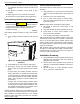
DANGER
Electrocution. High voltage is present at
transfer switch and terminals. Contact with
live terminals will result in death or serious
injury.
(000132)
DANGER
Electrocution. Do not manually transfer under load.
Disconnect transfer switch from all power sources
prior to manual transfer. Failure to do so will result in
death or serious injury, and equipment damage.